


“Monsters From the Id!”
Recreating the First Movie Star Ship (originally written in 2013)

The final build up of the new C-57D kit from Polar Lights/Round 2 with surrounding art realized by Jamie Hood.
This project all started when Jamie Hood at Round 2 decided they should make a new kit of the C-57D from the classic “Forbidden Planet” film of 1956. The determination was made based on two factors: The older 1/72 scale kit was very large… too large for many people to actively display in their homes, and second, although wonderfully comprehensive with its interior detailing, the accuracy problems with the exterior shape of the older kit was the source of many complaints.
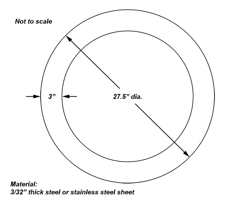
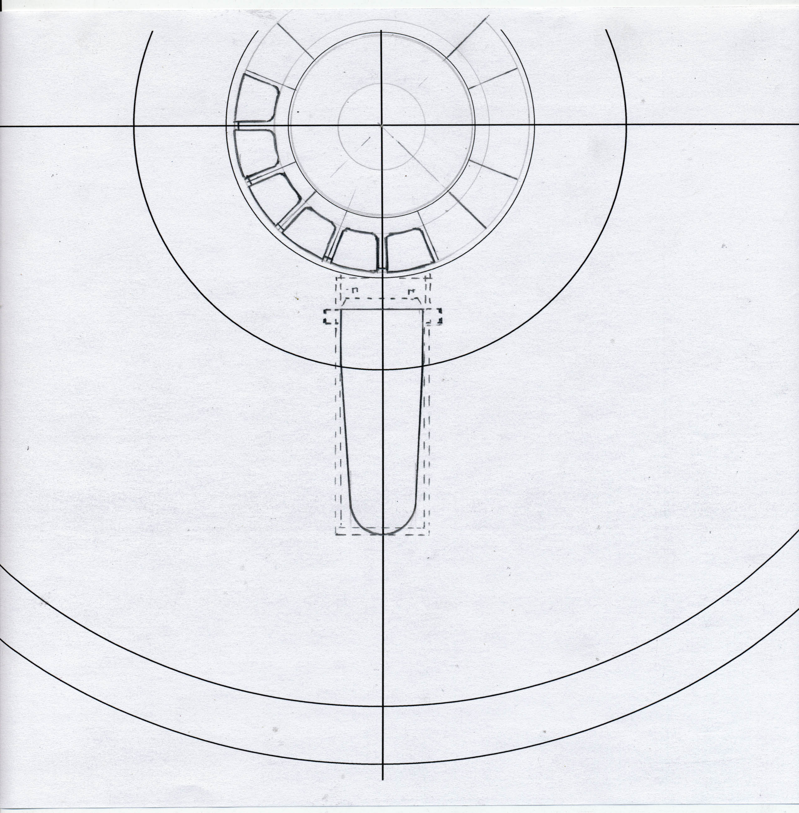
I had built this older kit for Round 2 when the re-released it some years ago with new features, but the problems with the way the kit was necessarily made, with its main saucer shaped bulk made like a cut up pie, caused problems with warpage and getting rid of the seams that were obvious with joined parts. To correct the warping problems prevalent at the outer edge of the saucer, I had a friend of mine who worked at a metal manufacturing company cut me a large steel ring using their CNC laser cutting machine that would be placed inside and act to straighten out the edge. Unfortunately I never took pictures of that (or I simply can’t find them right now) but here is the plan I submitted for the ring to be cut.
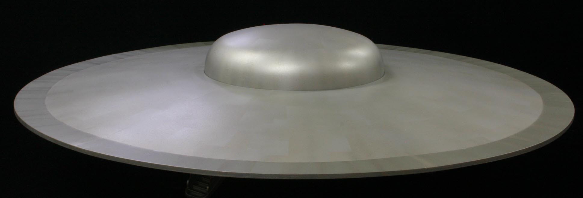
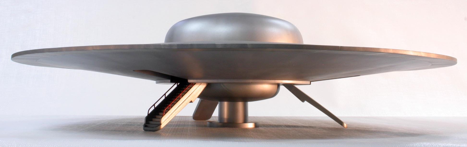
The model was assembled and painted as per the instructions with the only modifications made to allow the ring to be installed, like cutting away locator pins and so on, and a LOT of puttying and sanding to hide the pie-shaped joints. Although in the film, the VFX model was extremely plain and unweathered, I used artistic licence in the paint work to make it look more interesting and help hide the joints between parts. The finished model can be seen in these pictures. Although the full interior was also built it’s not shown here. If I were to do the kit again, it would have the interior done as a cutaway and NOT installed in the main model so it could be made more visible, as most of the interior details when assembled into the model cannot be seen, which is a shame.
It was decided a smaller version would be warranted and Jamie gave me the job of researching the craft and designing a new kit that would fit the bill.
I am assuming that Jamie liked the work I had helped with on the newly released 1/350th Starship Enterprise and I was happy that he considered me for the job. Naturally I was excited at the prospect of designing a new kit, but a few things needed to be hashed out. First, what size to make it? Tooling considerations were put into account, as the size of the tool determines much of the cost. A 12 inch diameter model was considered optimal.
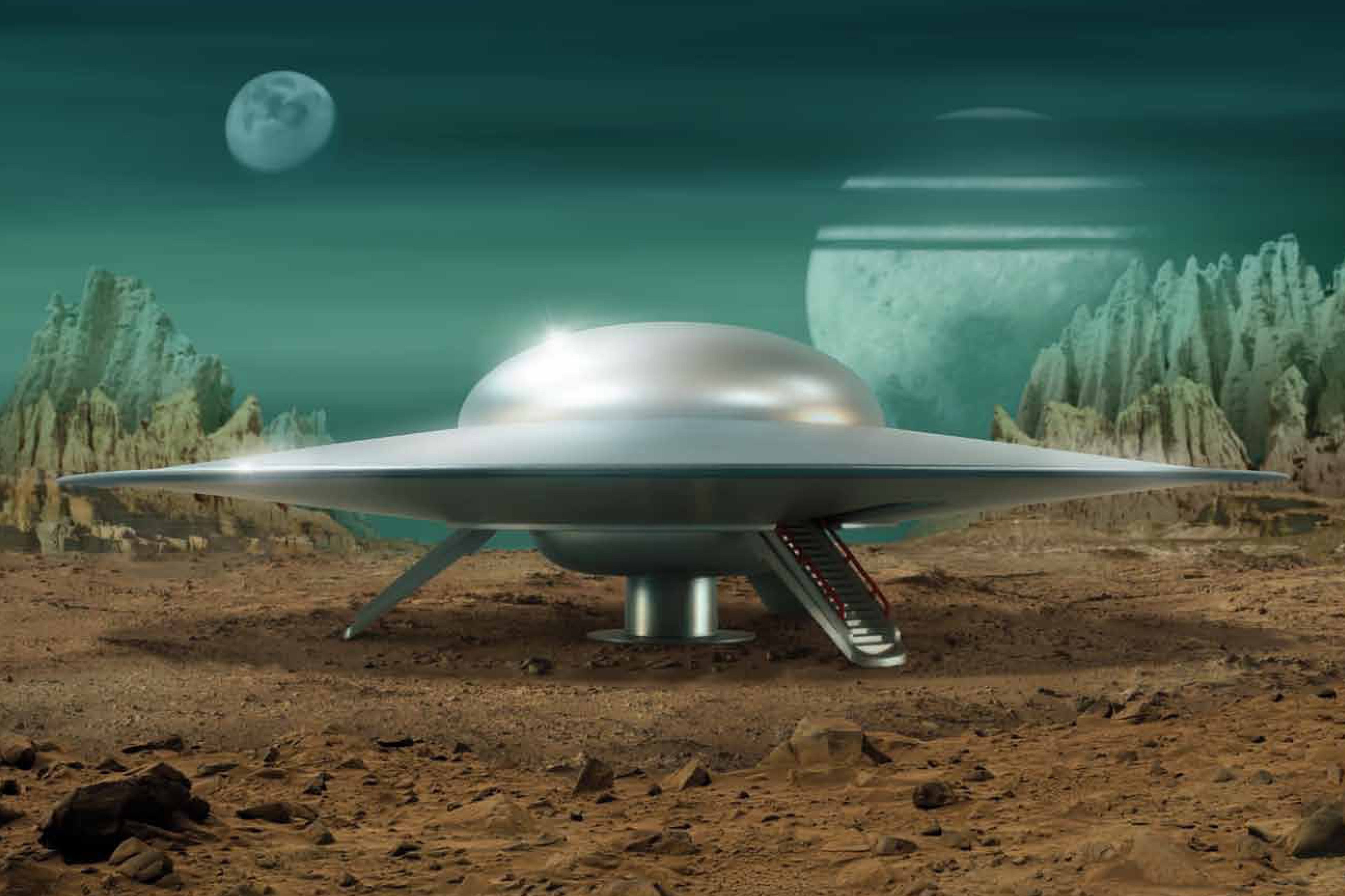
So what scale would a foot diameter model of the ship be? There are many conflicting accounts as to just how big the “real ship” would have been had it existed as something other than a studio set piece and a series of visual effects miniatures. The studio miniatures did not match up exactly with the full sized partial set that the actors performed against, and we certainly know the interior of the ship as portrayed on the sound stage would never come close to fitting the exterior of the craft as portrayed on screen. This is very typical of the numerous cheats that are made in films, so a compromise had to be made for our little kit. We opted to completely ignore the interior set and many aspects of the full sized exterior (of which only the bottom half was constructed anyway) and concentrate solely on the largest of the VFX miniatures, specifically, the “hero” model that you see touching down on Altair IV.
Based on what logical evidence we could glean from all various sources, we figured the 12” model would be close enough to 1/144th scale that’s what we decided on. Sorry to burst anyone’s bubble, but the fact is, sometimes there is no perfect scale that determines a fictional movie ship’s size or scale! Remember that the models and props built for films are simply designed to provide an image that mentally coincides as accurate within the context of the story during the few seconds you see it. Things are NOT always mathematically calculated out to work as they appear to. It’s just an illusion on film. Anyone that wants to argue about the scale of the kit is welcome to present the real and fully functional starship and prove their point. Our mission was to create a model kit that accurately matched what you see on film as a representation of the fictional craft. We think we got as close as reasonably practical.
The next step was to get an accurate profile of the model that we could use to get the proportions correct. We had access to some pictures of the existing VFX miniature but we were not able to contact the current owner (we didn’t know who owned it anyway) and the pictures we had, although helpful for some details, did not show an accurate profile. So I turned to the film itself, as the shot of the saucer landing on the planet just happened to present us with a near perfect side profile with little parallax error! So I simply used a screen grab of the image from the film and loaded it along with a few other shots of the model as a backup “proof” into Photoshop and began to work out the geometry.
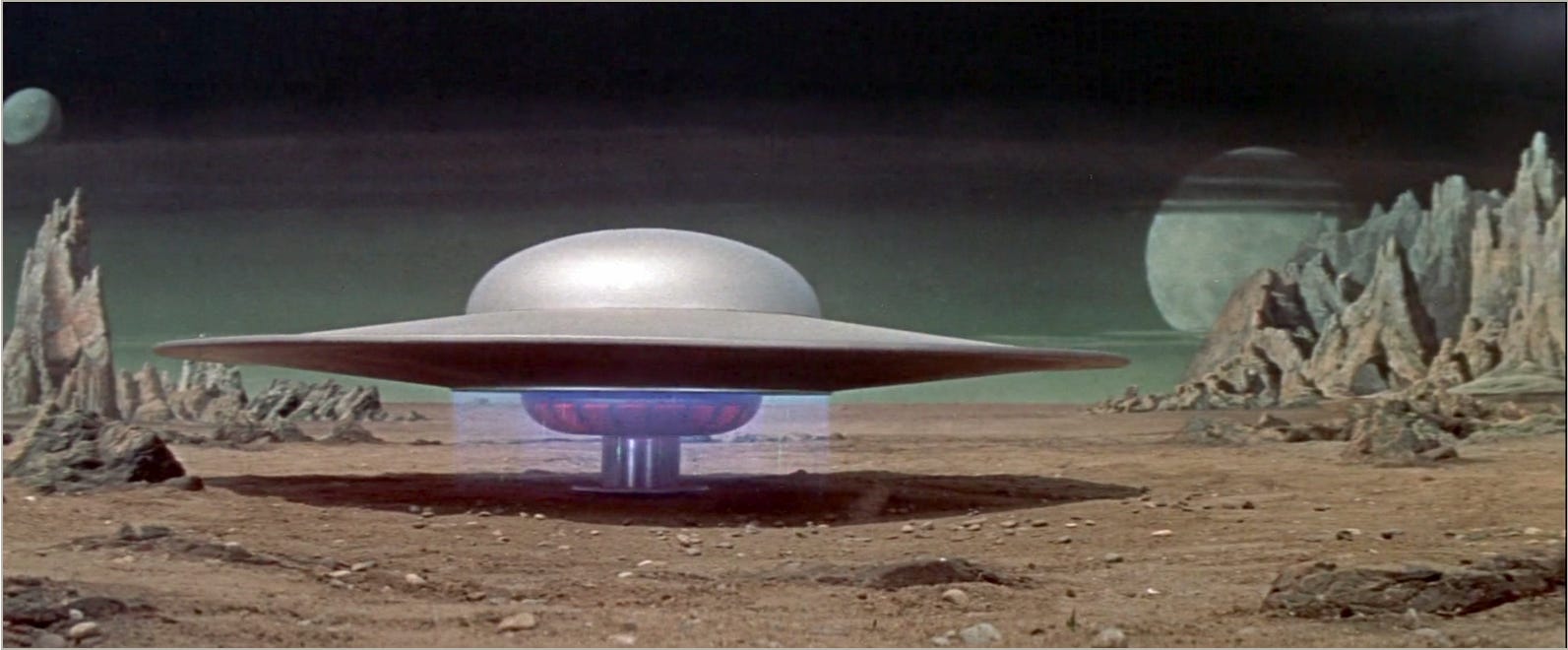
The screen grab that provided most of the correct proportions of the model
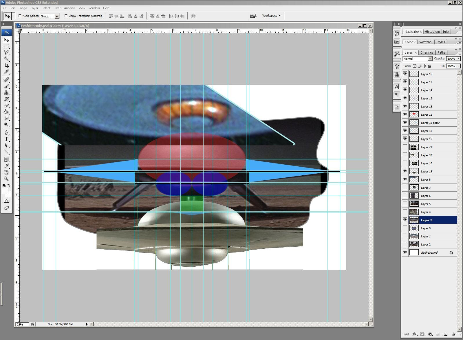
Many photos brought into Photoshop and scaled to relate all the critical measurements and proportions needed to determine kit accuracy.
I discovered after some study that the profile was indeed made of basic geometric shapes. This is not likely a coincidence, as no doubt the draughtsmen who made the drawings of the ship for the original models’ construction found it easiest to use standard geometry to keep all the models consistent. The top dome is actually made from a perfect elliptical cross section that is twice as wide as it is tall sliced horizontally to form a cap. The bottom dome is made from two ellipses rotated around a central axis and sliced similarly to form the engine’s “reactor” core. Triangles obviously made up the main saucer “wing” with the rest of the ship designed by simply tying these parts together as shown here.
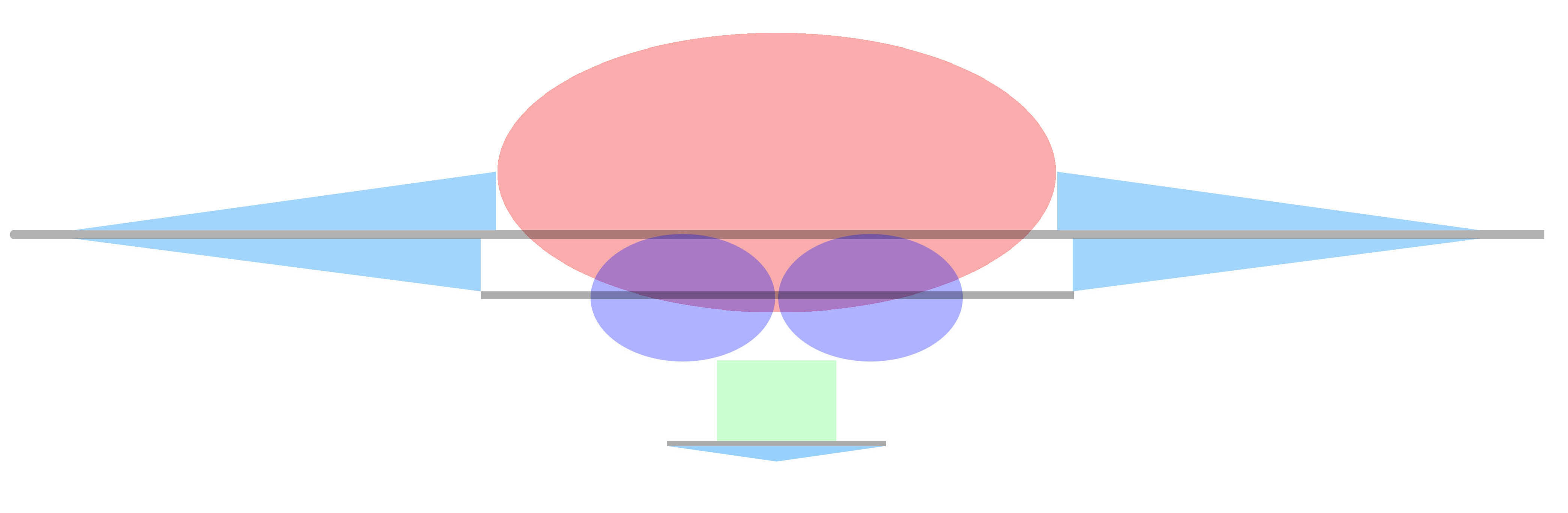
The basic geometric shapes that make up the ship
From this study I printed out a full size (12” kit) version from which I could make sketches and work out the sizes of all the accessory parts like the landing ramps and interior mechanisms to make them work. I still like to do things with good ol’ pencil and paper which is often more relaxing to work with especially for basic layouts.
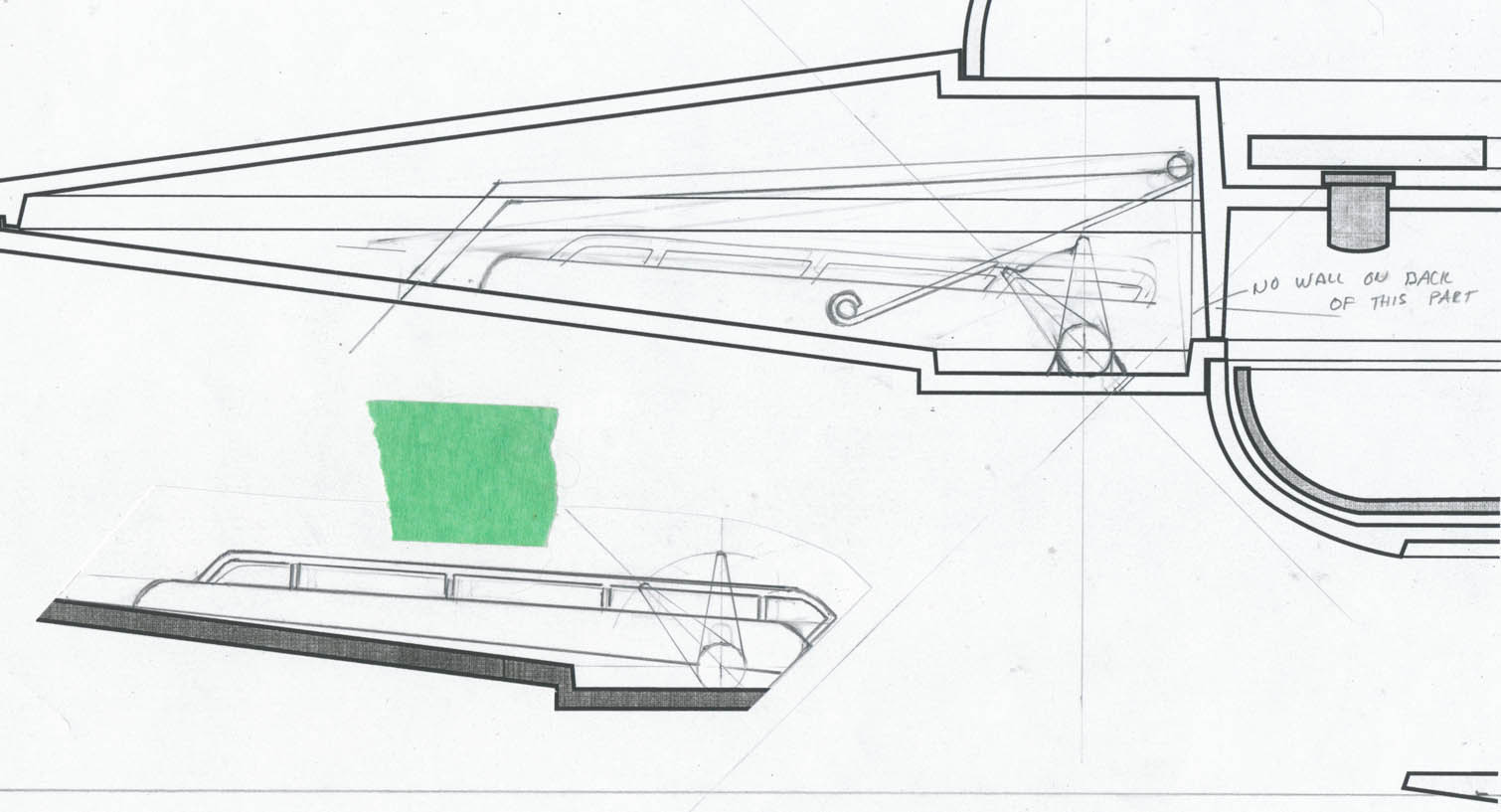
Working drawings sketch done on graph paper to work out mechanical details.
Going back and forth between these sketches and Adobe Illustrator I worked out all the parts for the kit, making sure to stay within the confines of the shapes determined to be most accurate. Changes were made as I progressed and things ironed themselves out.
Once I had the bulk of the understanding of these parts worked out in my head and on paper, it was time to do the final drawings of the kit for the factory to use. The factory was going to be using these drawings as a guide to building the CG model which in turn was going to be used to make the prototype resin 3-D mock-up and then carve out the final steel tool.
Years ago I was a professional mechanical draughtsman and technical illustrator by trade before doing my first love of modelmaking for a living, but doing full blown “blueprints” that one might expect was not necessary, knowing how the factory worked. For some things, like locating pins and some areas of fitment, these were items the factory would flesh out while doing their CG model. All I had to do was essentially tell the factory how the model was going to work and what limitations there were as far as dimensions, functionalities and builder-friendly aspects go. I have a reasonable understanding of mould making and tooling (I was also trained as a basic machinist), but the factory of course has more experience and understanding of their own capabilities, so just a good interpretation of the model was all I needed to provide for them.
One of the things I learned long ago about drafting is that “anything you do that makes it easier to make the part, even if it goes against standardized conventions, you do it.” So, realizing how things are done these days compared to what they were like when I was first taught, I set about making up colour coded and labelled drawings in Illustrator, detailing all the parts and how I thought they should be designed, knowing that the factory may have to come back with subtle changes to be made anyway. I knew, for example, that even though basic dimensions can be followed, it’s easy for modern CG modelers to superimpose a drawing on their virtual workbench and trace it to make their 3-D model, so many normal standards such as call-outs and labelling every possible dimension could be thrown out, thus saving time, making things clearer and less complicated. I also prepared a written document describing how the parts should all work together (see separate PDF document posted below if you are interested).
So I created a series of drawings in Illustrator (below), drawing all parts to scale and making labels only where necessary. (Click the images for a larger view)

The main profile with all critical measurements documented.

The cutaway showing all main kit parts and inner workings

Basic working drawings, done to scale, of all components of the kit with options noted. Some of these parts ended up having some modifications done and do not perfectly match the final kit.
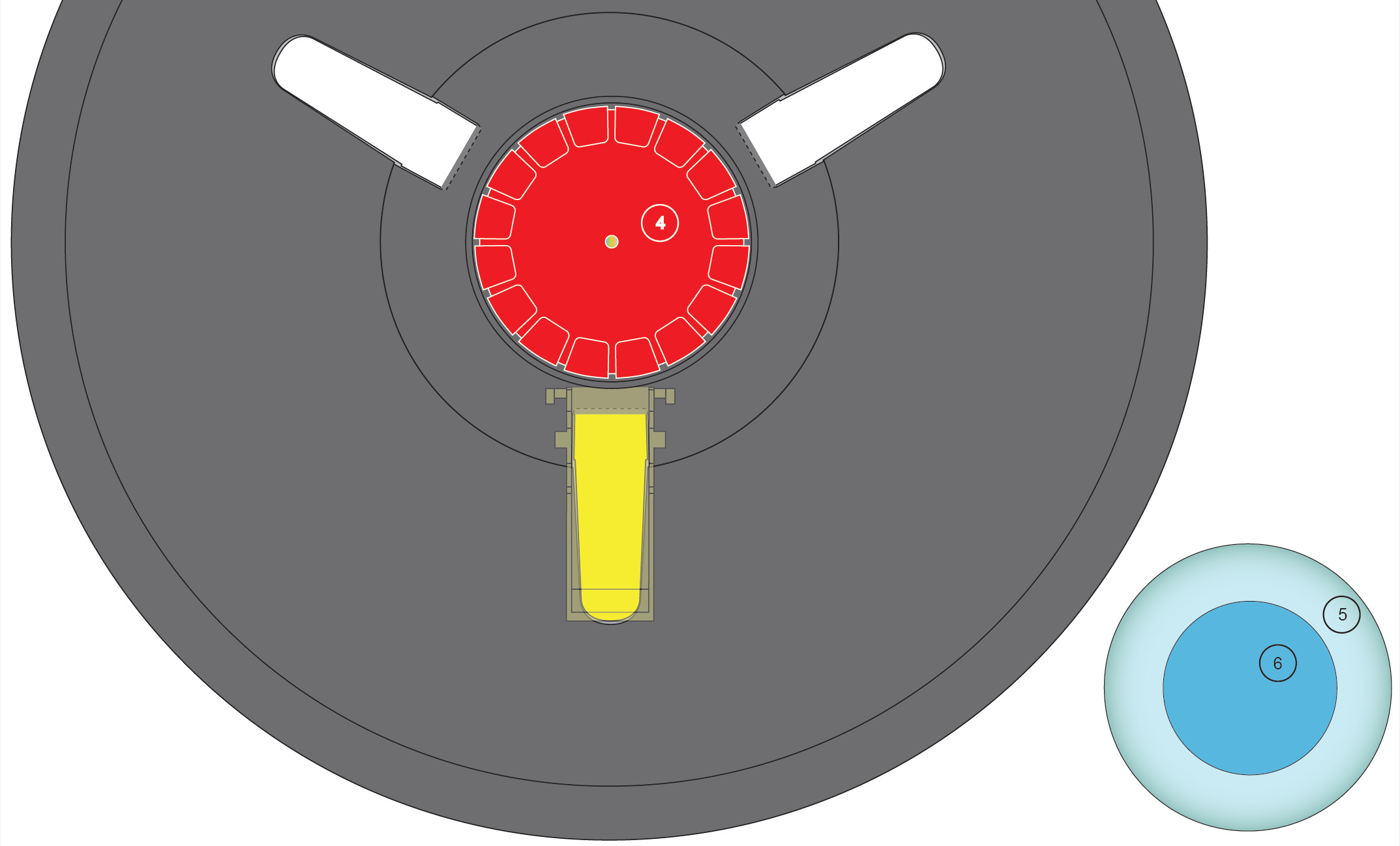
The bottom of the ship, showing the reactor core parts with hatch sizes and locations.
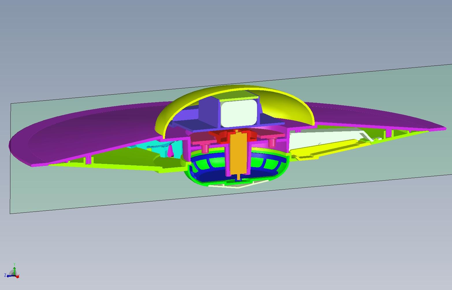
From these drawings and the text document provided to them, the factory came up with the CG model which included all parts breakdown for us to examine and approve. Except for a couple of errors (which turned out to be my fault and were quickly corrected) the CG model matched what I had drawn nearly perfectly, and the whole thing worked! The go-ahead was given to then produce the resin prototype made using stereolithography, also known as “rapid prototyping” or “3-D Printing” which is very quickly becoming more commonplace and affordable, making guys like me nearly obsolete! (Computers love doing that don’t they?)
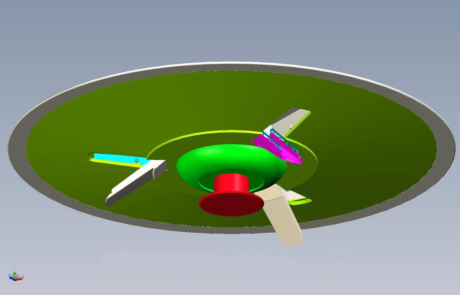
CG model developed from the drawings.
When the prototype arrived at Round 2, Jamie and I held a video conference using Skype to allow me to examine the model second hand without having to go through the time and expense of shipping it directly to me. It turns out there were no problems whatsoever with the way the prototype worked (I was most concerned about the spring mechanism I had designed to ensure that the landing hatches would correctly snap into position with no play or wobble) and we were both happy with the results. The factory had also made some changes regarding the way the “reactor” was constructed, opting for separate little windows instead of a once piece core. The go-ahead was given to the factory to begin cutting the tool for the final styrene product.
So, we waited……
When the tooling was done, the factory ran off test shots for our approval. I was sent three complete sets to examine and build to make sure everything worked OK and Jamie was also sent a few sets.
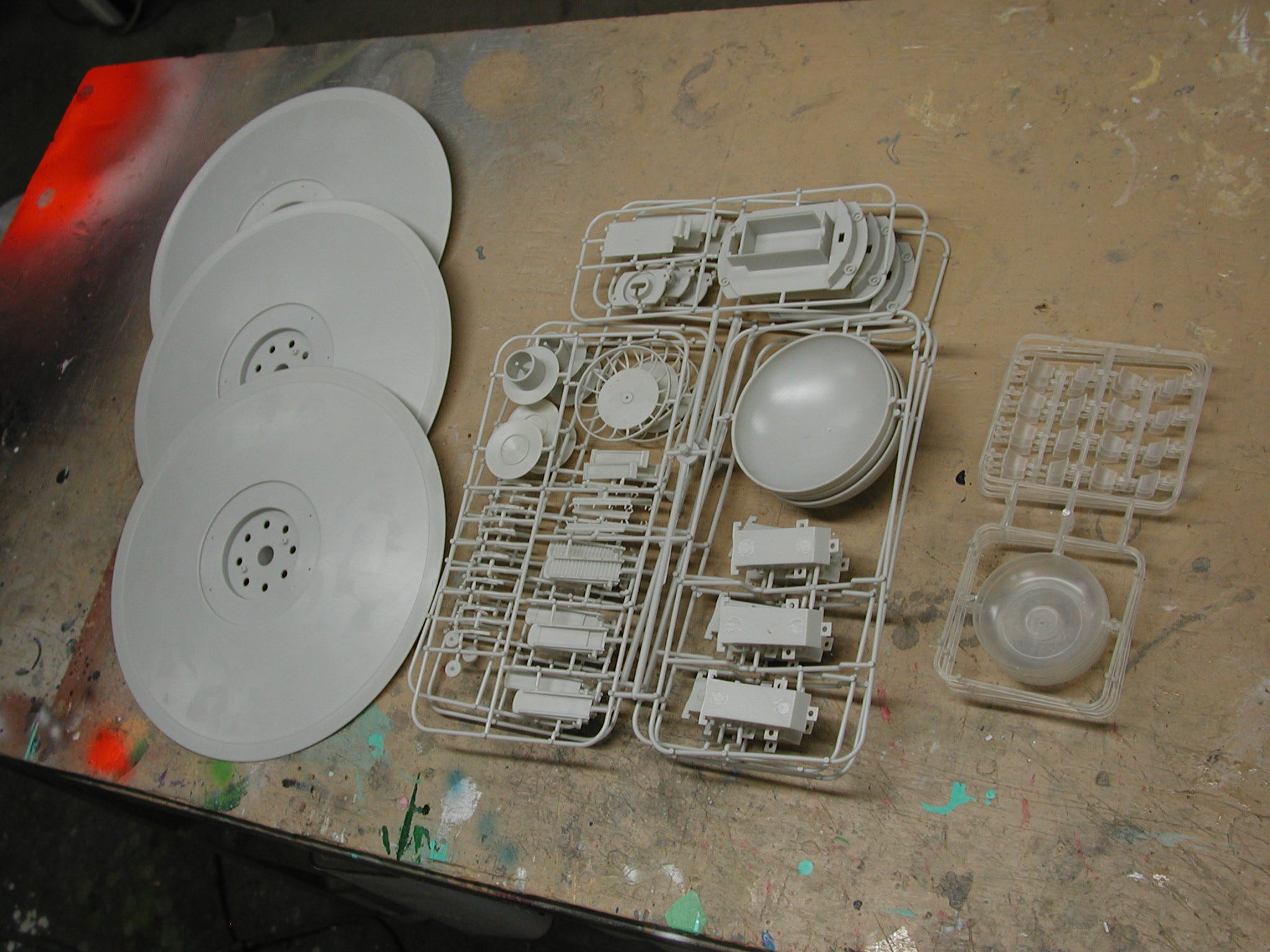
The 3 test shots as they arrived after unpacking
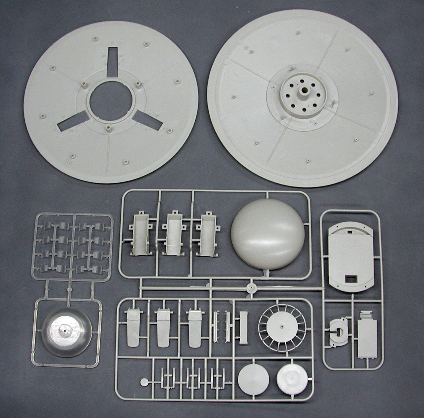
One complete (deluxe) kit parts layout minus the electronics
The test shots went together almost flawlessly with only a couple of very minor changes needed to strengthen the springs that hold the hatches in position. So I built two kits completely finished for display.
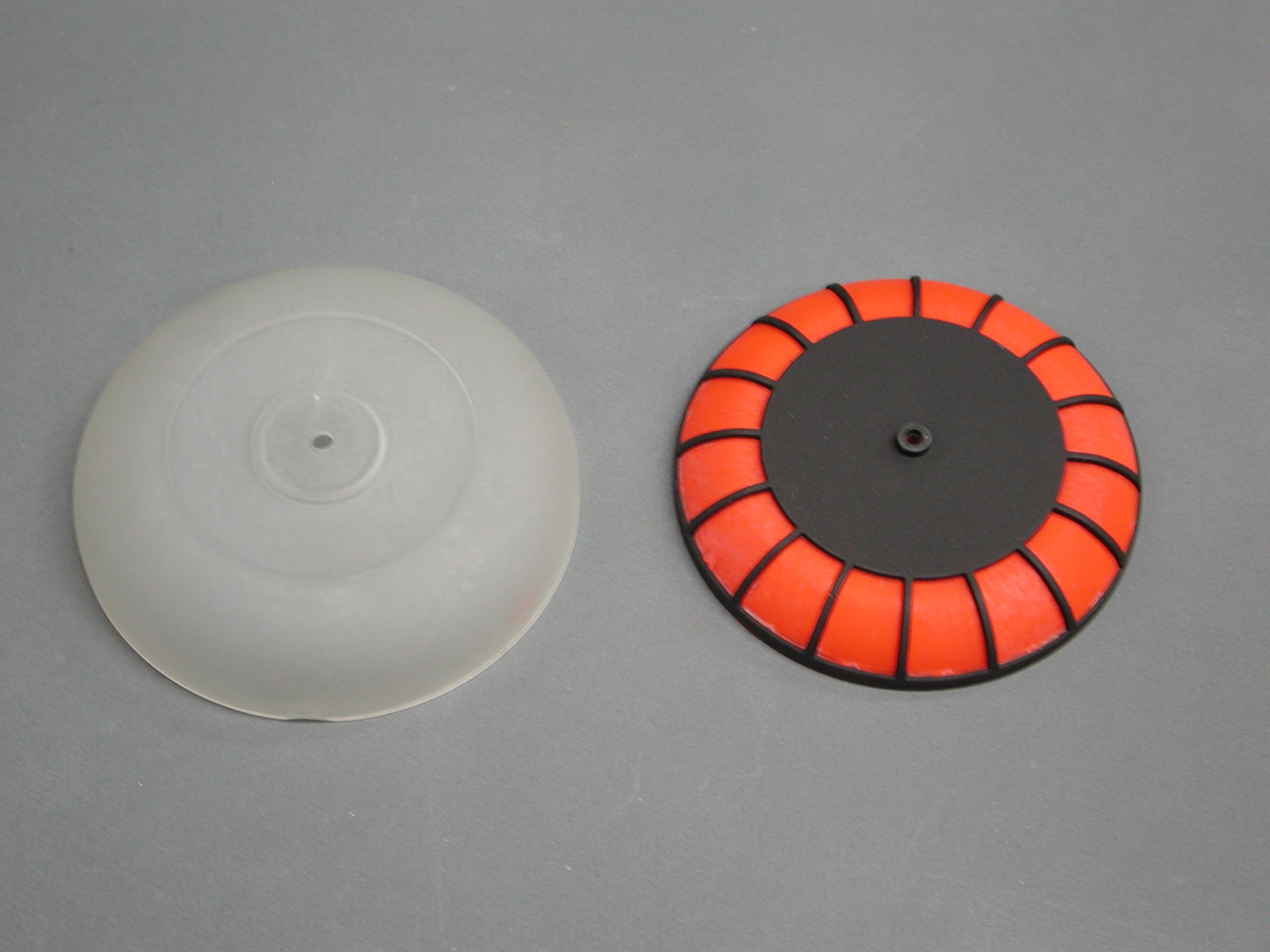
Testing unlit version with fluorescent paint.

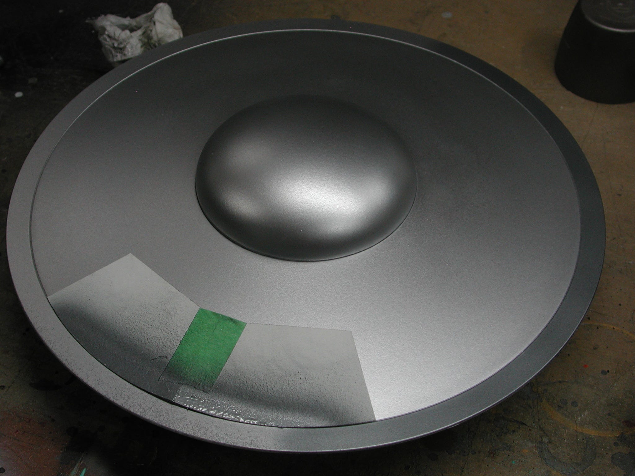
A quick way to paint the outer ring with its gun-metal colour.
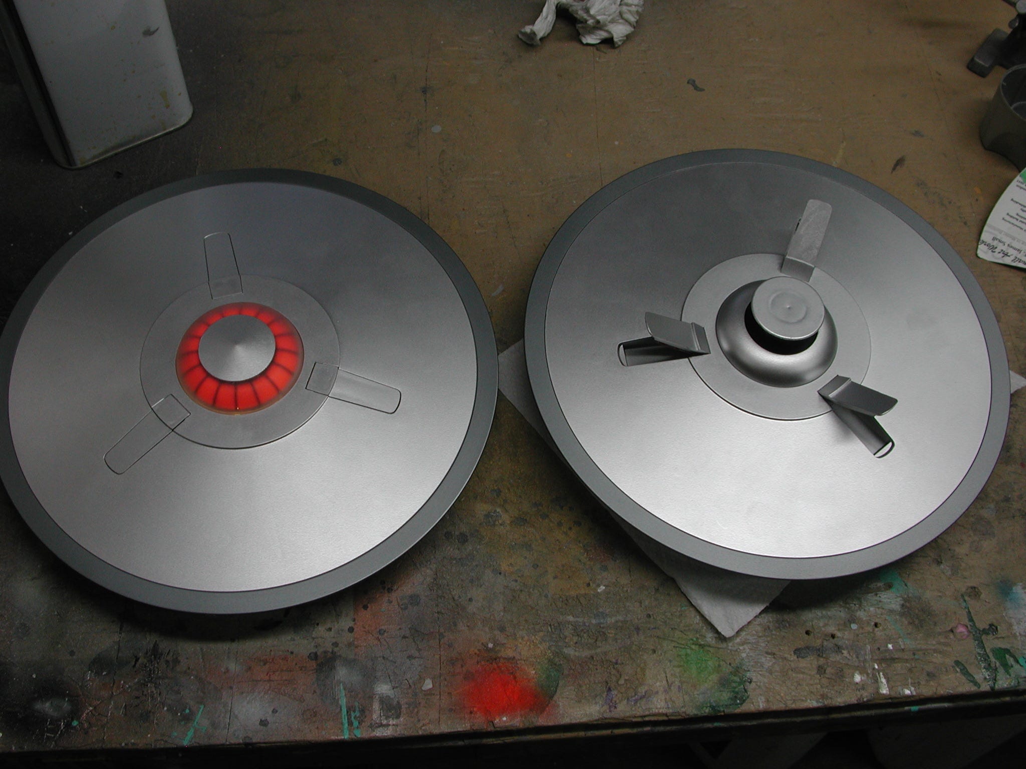
The finished models
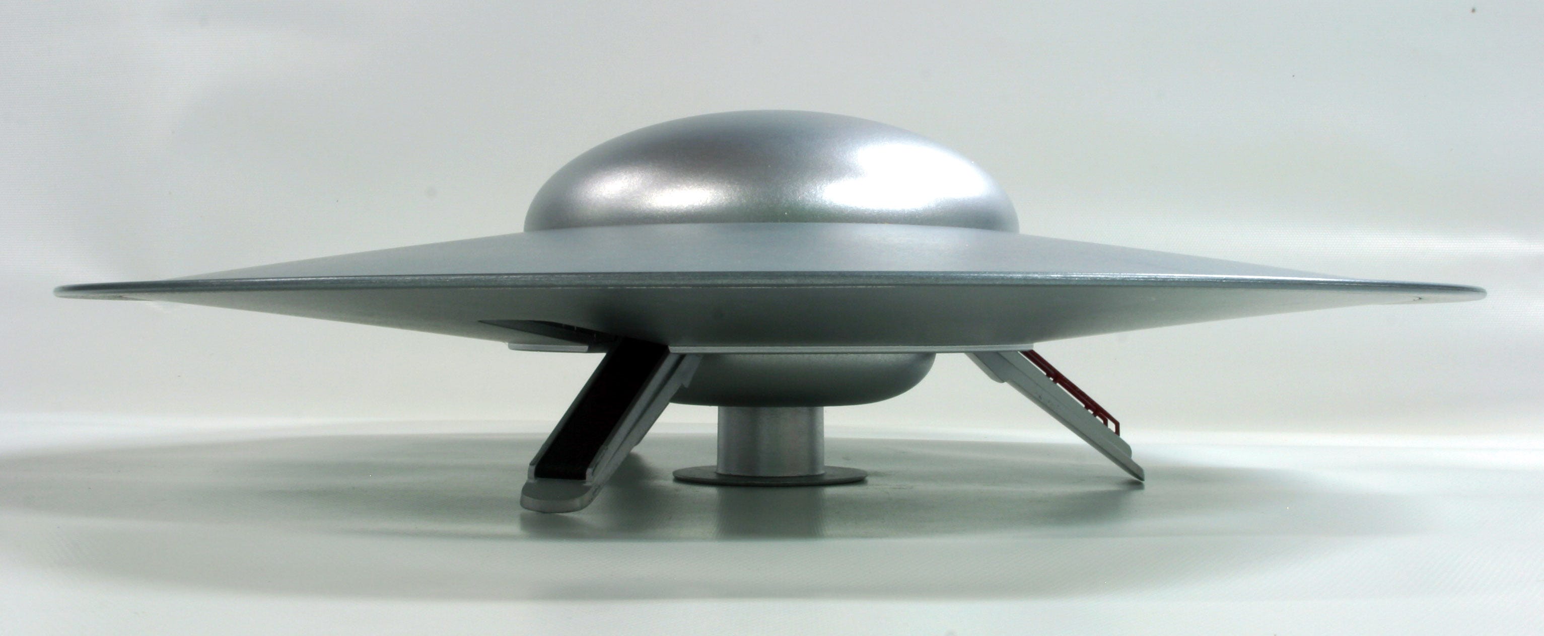
One as the “standard” kit with the landing gear down and sitting on the ground, the second in the flying position with motor and lights installed and a modification made to allow it to be mounted to a stand I had made.
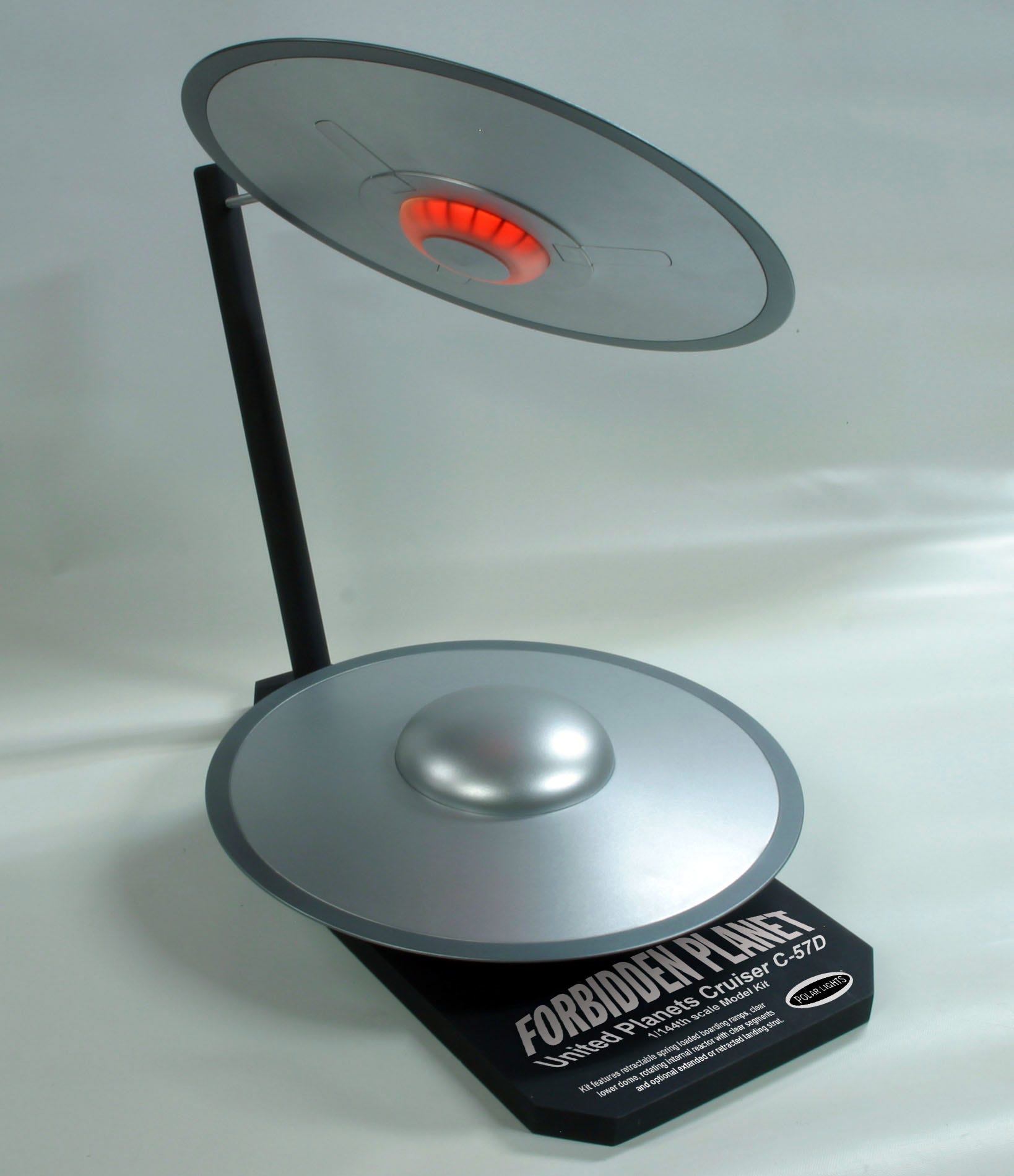
It’s important to note that I although I had designed the kit so that the builder is able to configure it in either mode, as parts are either replaceable or movable, for Round 2’s display I thought it best to make two separate models so someone doesn’t have to constantly move them back and forth from one position to the other!
Although I had designed and mastered a number of successful resin kits in the past, this marks the very first model that I had ever designed from the ground up to be made into an injection moulded styrene plastic kit for entry into the mainstream mass market. I got a personal thrill out of doing this and I hope to do a lot more projects like this in the future!
Special thanks to Jamie Hood and the guys at Round 2 for not only making one of my personal dreams happen, but for allowing a kit like this become available. And from what I have read online so far, a lot of people really like this new version of the C-57D! For that I am also grateful!
Happy building, and please make sure you visit the rest of this Newsletter page and visit www.smallartworks.ca for more Excellence In Model Building.
Brilliant, as always!