Space Balls, Part Deux... The Conclusion!
Finishing off my clients' pair of balls from "2001 A Space Odyssey".
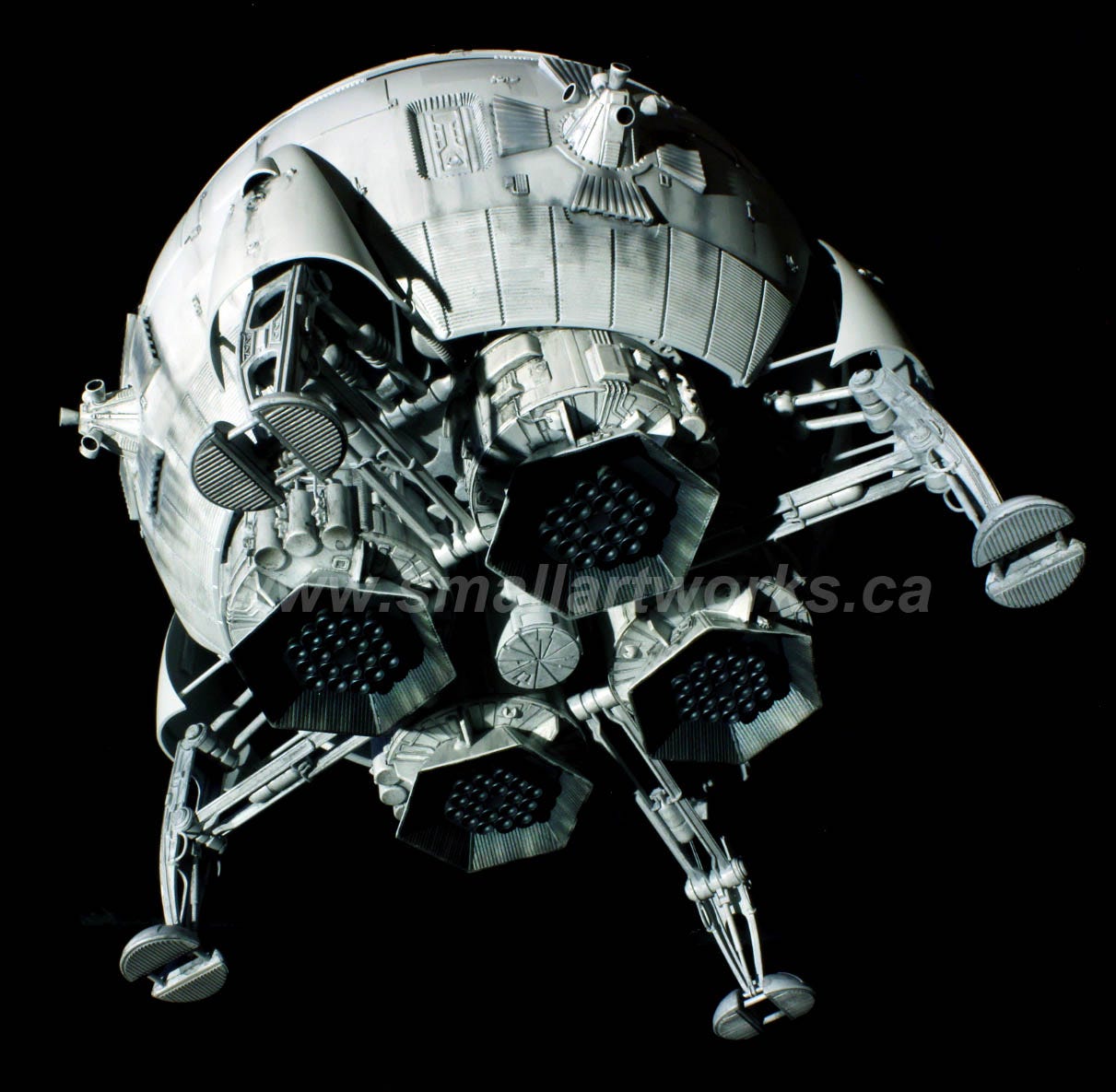
This following shot, BTW is of one of the models I finished. Not from the film itself.
Here we are with the final stages of getting these two models built. I had some other projects in between this and the previous post so that’s why it took so long for this update. For this build, I wanted to make sure that in case something got damaged some time in the future, the model could be serviced to repair components that have either failed or got broken. Given the extremely fragile nature of this model I figured that to be necessary. That meant taking extra steps to put as much together with screws and/or magnets instead of glue so that it could be taken completely apart if needed. As explained previously, both models were built for two different customers and they had subtle changes made. The photos show both models at random which explains slight differences between the two. Keep in mind that the size of the finished models is about the size of a basketball.
Let’s get started with the pictures which are mostly self- explanatory.
REMEMBER… you can click on all the pictures shown here if you want a larger higher resolution view.
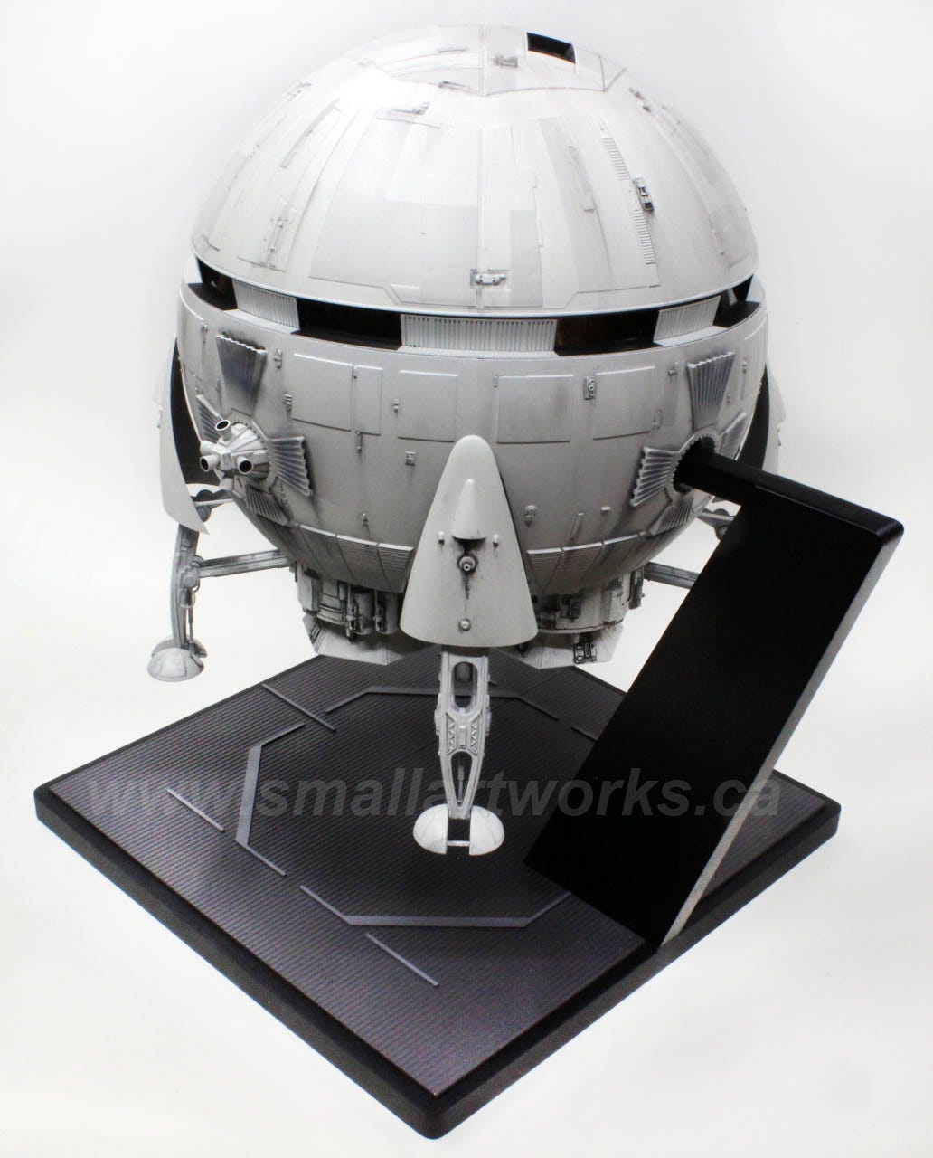
Here (following photo) is the very basic stand and scratch built armature assembly showing how the model can be plugged into the stand in three locations which is made from MDF with a hardwood post. The fourth quadrant will be occupied by the battery pack and distribution board so there was no room for a fourth mounting point. The unused mounting points will simply have the small attitude thrusters plugged into their place. This armature allows the model to be displayed in the “landing” or vertical position or “in flight” horizontally.
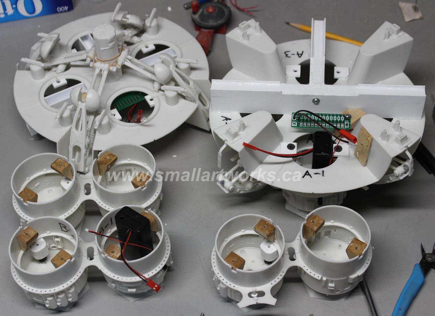
This next photo shows both models under construction with the modifications required for servicing. You can see how MDF blocks were glued to the engine cylinders to admit screws from the inside hull, the distribution boards installed and the battery pack with relevant wiring. In the top left quadrant of the photo, the landing gear struts are held in place temporarily with elastic bands at the centre to keep them from flopping around while being handled. The rough block of wood you see at the right of the picture (glued to the rightmost landing gear well) that seems to be doing nothing special was an example of “designing as you go” which is the only real way to do this kind of thing. I was originally going to attach the distribution board (the green PCB) there but then realized that you could not access the screw that holds it in place once the main body shell was glued surrounding this chassis. So I removed the block, but some residue was left behind as Cyanoacrylate glue is rather tenacious. Since it’s inconsequential, it doesn’t really matter that I left some of it behind after chopping most of it out. I instead installed the PCB (with only a couple of wires shown soldered in so far) in a horizontal position you see here.
This picture shows the main lounge floor panel in place. The lower yellow “walls” are secured with screws as well. Screwing things in place was not only good for future servicing, but it also allowed me to put things together while figuring it all out, yet allowing me to remove them for ease of painting. It is often easier to paint parts when they are separated from the main assemblies. Note the switch in the centre of the engine cylinder, disguised to look like some of the mechanical detailing on the model. It will be less noticeable when everything is painted and weathered. I also used JST connectors throughout so all wiring can be separated at will if needed for servicing.
Here is what it looks like with the outer body shell glued in place. This HAD to be glued, So I had to design the rest of it to be accessed to this point. The screws seen popping proud of this section are the ones used to hold the lounge deck in place. Blocks were made and glued in place, made from plastic sheet and MDF to accept the needed screws. Figuring out where the screws had to go was extremely time consuming and carefully planned out to make sure the modifications were not going to interfere with the way the rest of the kit was to be assembled. Note how the engine cylinders are now held in place with screws, and can be accessed by removing the lounge section. The batteries can be accessed by simply removing the engine exhaust baffle which is held with magnets (shown in he previous posting of this model)
This next shot shows how the finished interior looks with the dome removed. Note the wiring (connected with a JST plug) that provides power to the ceiling and cockpit section. Magnets surround the perimeter of the ceiling and are attracted to flat head drywall screws placed into the perimeter of the lounge section to hold the dome on when placed on top.
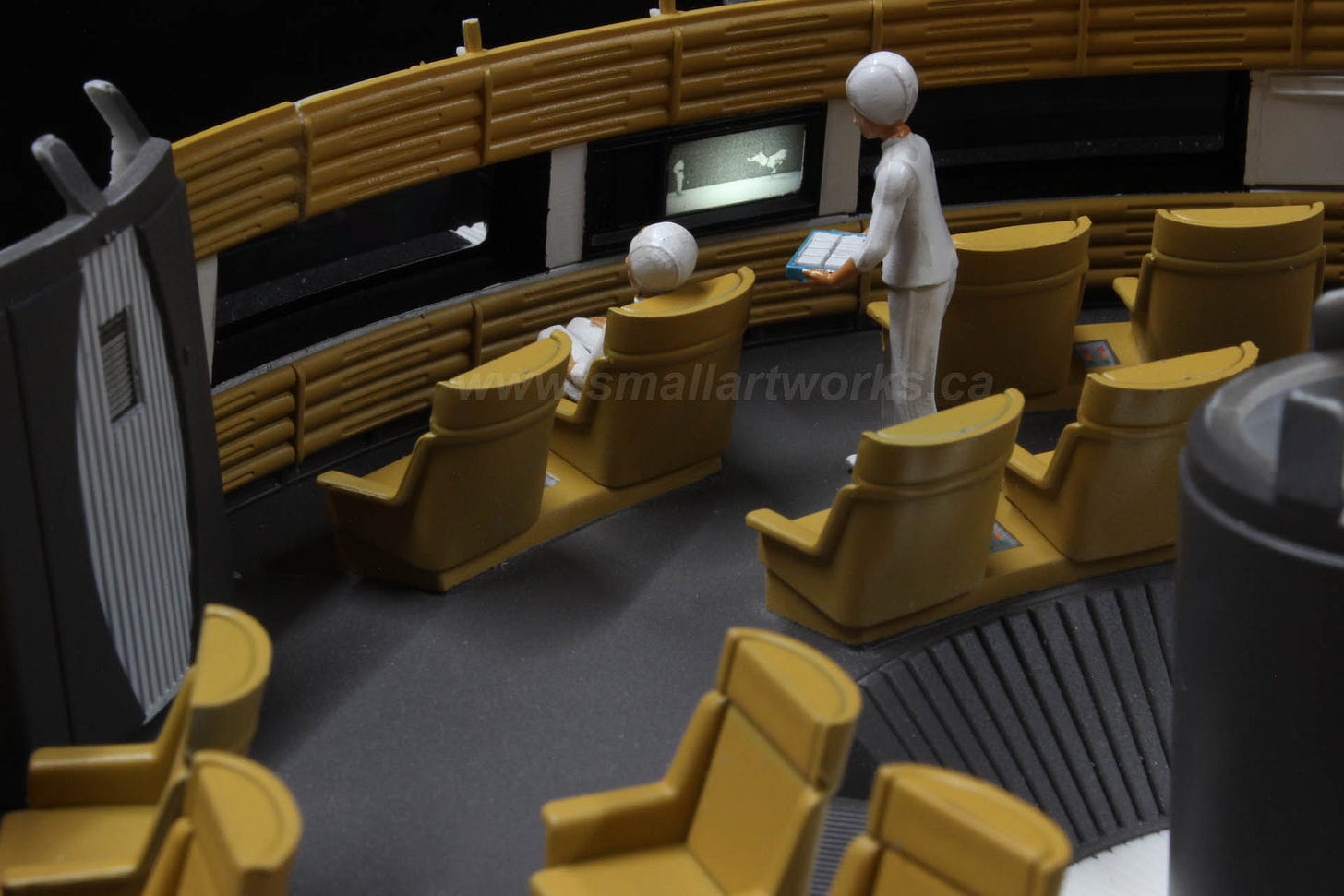
Here is what the finished interior lounge looks like with aftermarket figures installed. Note the lit-up stairs, centre floor and elevator section. Two stewardesses interact while Heywood Floyd, strapped into his seat, enjoys a zero-gravity lunch. Why are most of the seats empty? Well, watch the film to get the context. To the point, it was a special flight for Floyd, a VIP, so no expense was spared.
One of the stewardesses, as she is about to be served a meal by her counterpart, is watching some sort of Karate demonstration on a widescreen TV which has a flickering LED installed behind it to give the impression of animation.
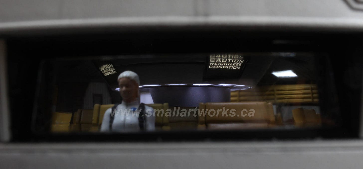
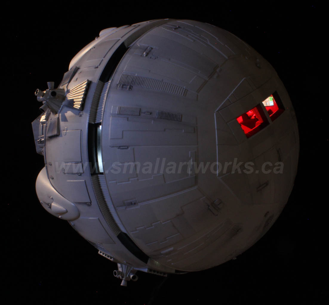
When the model is fully assembled you can peer though the outer windows (which are a little distorted because they are not optically pure plastic) you can see that the interiors are remarkably realistic given the tiny size of the model. The lighting really does match very closely what was seen in the film!
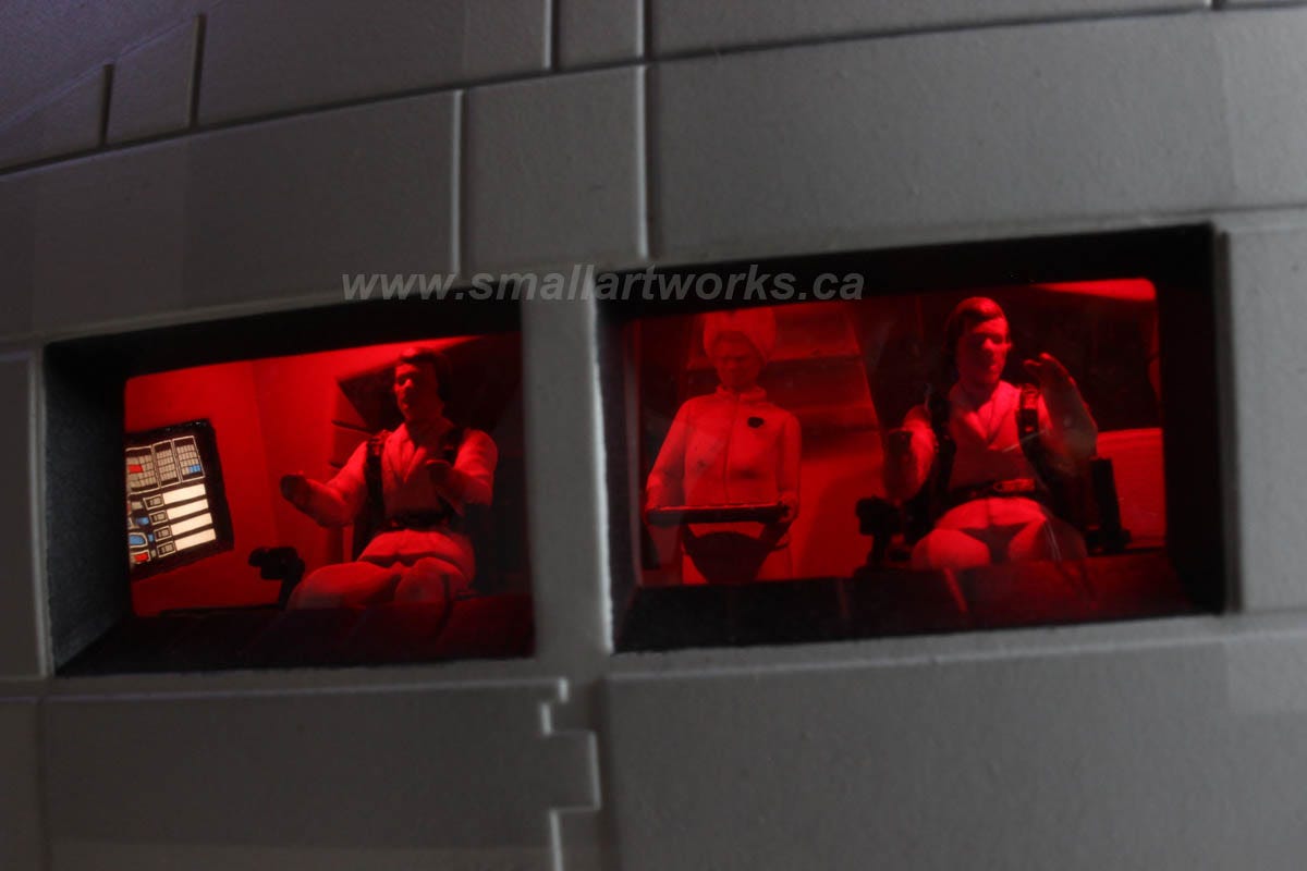
The cockpit section lit by red LEDS as seen the film. Note the separately lit side instrument panel
I know you’re asking… why are the pilots punching the air? Well, they were obviously talking about the famous boxing match of Lennox Lewis vs. Hasim Rahman which took place at the time. ;-)
Seriously… that’s just the way the aftermarket figures were molded. They should be grasping the control sticks just below their fists, but the 3-D printed and VERY BRITTLE figures simply didn’t allow themselves to be easily modified to fit properly. As it is I had to grind and sand their butts and thighs down just to fit the seats! When the model is sitting on the shelf or on display on the stands (see below), the figures are barely noticeable anyway without extreme scrutiny (It was difficult to get these pictures as it is) so it’s one of those “yeah… whatever” kinda thing. Still looks very realistic for its size, so it does the job.
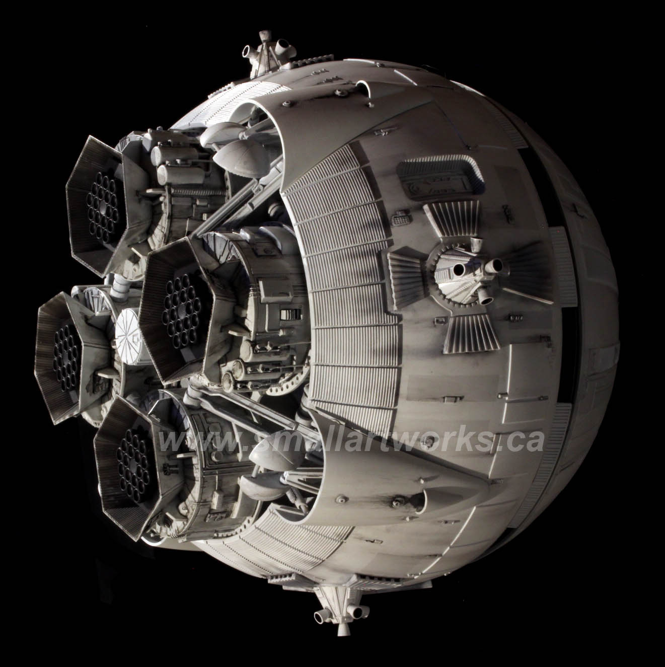
Here are some more pictures of the finished models for your enjoyment. Please share and subscribe to this Small Art Works newsletter page to see more interesting projects in the future. Hope you enjoyed this one! Thanks for reading!








Fantastisk !
You. Sir ! Are Brilliant - Lots and lots of god vibes to you