


Thunderbirds are GO!
(Well, ONE of them is right now anyway!)

My friend Daniel asked me to build a model of Thunderbird One (TB1) for him. So, of course I said…NO! (Just kidding!) He had collected a few kits of this favourite Sci-Fi craft. This model of TB1 was released by at least three different companies… Aoshima, AIP, and DeAgostini. They are all identical except for the DeAgostini version which was molded in three colours. The one discussed here is the AIP version. Dan sent me the kit so of course the first thing I had to do was research, which I usually do for most models I build. I found the high definition version of the Thunderbirds TV show and looked through a couple of episodes to get some good reference of the fictional aircraft.
It’s important to note that the miniatures used in the show were of multiple scales (sizes) and were often re-dressed and changed as the show was produced, so that means what the ship looked like on screen also changed rather dramatically from shot to shot. The models were really very crude compared to what one might think a filming model might be, and they were heavily abused during filming. Some shots even showed broken parts that were not repaired because “Look we need to get this bloody shot right now! No time to fix the damned thing! Just shoot it! Nobody will notice!”. (They never realized that geeks like us would ever see high definition versions available for us to scrutinize frame by frame instead of the low resolution TV sets with no recording ability at the time!)
So a kind of settlement had to be reached. It would take too long to describe all the changes I discovered so I won’t bore you with that, as I am already too long-winded. Suffice it to say that if you were to show me a picture taken from the show and tell me, “you got it wrong here”, I will ignore you or pull a William Shatner on SNL and tell you to get a life. The idea was to make the model have the same “aura” as that seen on the low resolution TV screen as seen in 1965 and to finish it the way Dan wanted it to look. Which I did.
Anyway, enough of the historical crap. Let’s just jump, dive and leap straight into this model, OK?
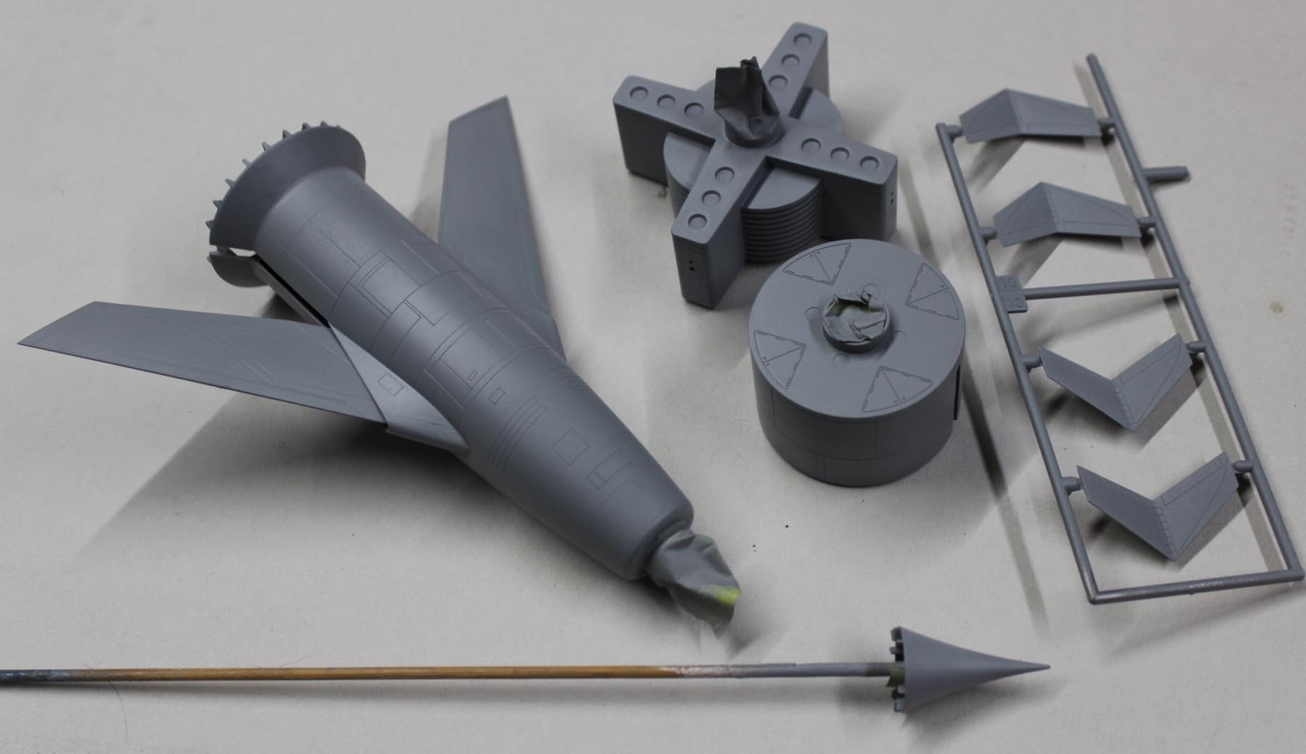
Here is a picture showing all the parts included in the kit as pulled out of the box.
One of the first things Dan and I discovered is that the decals provided with the kit were all wrong. Here’s an example of the decal sheet (still wrapped in its plastic bag here) compared to the boxtop showing a photo of the original miniature (Jeez, guys… you had one job...):
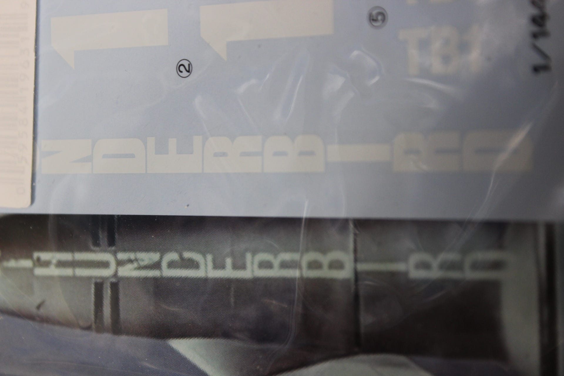
As you can see the text is WAY too thick and bulky and would have just looked like a white stripe running down the side of the model. Thus, extra steps needed to be taken.
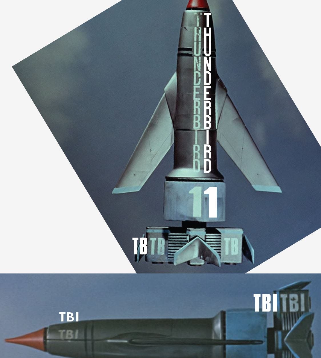
I spent several hours poring through thousands (yes, thousands, not just hundreds!) of online downloadable fonts to try and find the one that most closely matched the ancient Letraset text that was used on the original and finally found one that was almost bang on. Almost, because the alternative would have been to make all the letters completely from scratch which I wasn’t going to do unless Dan gave me a new car. To be sure I got it right, I used screen grabs from the high-def TV show files, used Photoshop to make these near orthographic shots to be exactly the same size as the kit and used them as a guide for size and shape of the lettering to match as closely as possible to the original. I built the text in Adobe Illustrator. I did have to construct and/or modify some of the lettering from scratch though. I think I got pretty close...
The resulting text was turned into a printable decal sheet with several sets added as backups and since Dan paid for them, he could have the spares for his other kits which also came with the incorrect decals. I also made new black stripe sections which wrapped around the cockpit section near the nose.

The art was emailed to Ben Sweezey at V1 decals who printed them out for us. He has the unique ability to print opaque and white markings that can’t normally be done with conventional Inkjet or laser printing, so he is always my first go-to guy now. If you need custom decals made, Ben is your man. Tell him I sent you. Or don’t. But I’d like it if you did.
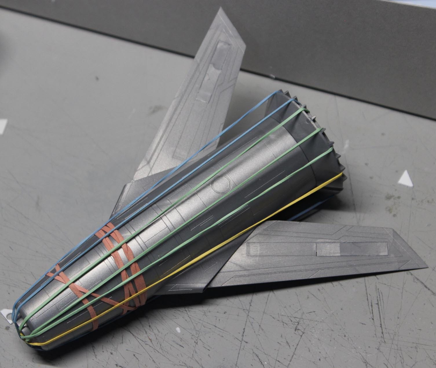
While I waited for the decals to be printed (which took considerably less time that Canada Post’s delivery service), the rest of the model was built. I started with gluing the main subassemblies together, as shown here. Elastic bands were used to keep the parts squeezed as the liquid cement solidified the plastic together. As this model was to be displayed “in flight” the included spindly landing gear parts (the kit has the option to build it in a landed configuration) were omitted and the gear doors were cemented into the closed position on the wings. Some trimming and shimming was required to get them to fit perfectly. Also, because Dan wanted the wings’ leading edges to fit flush to the rear body section when retracted (the kit as normally built allowed the wings to protrude), some trimming was required at the trailing edges of the wing root.
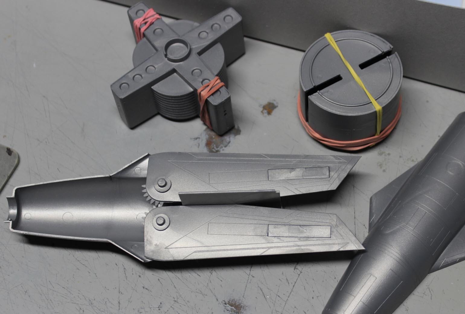
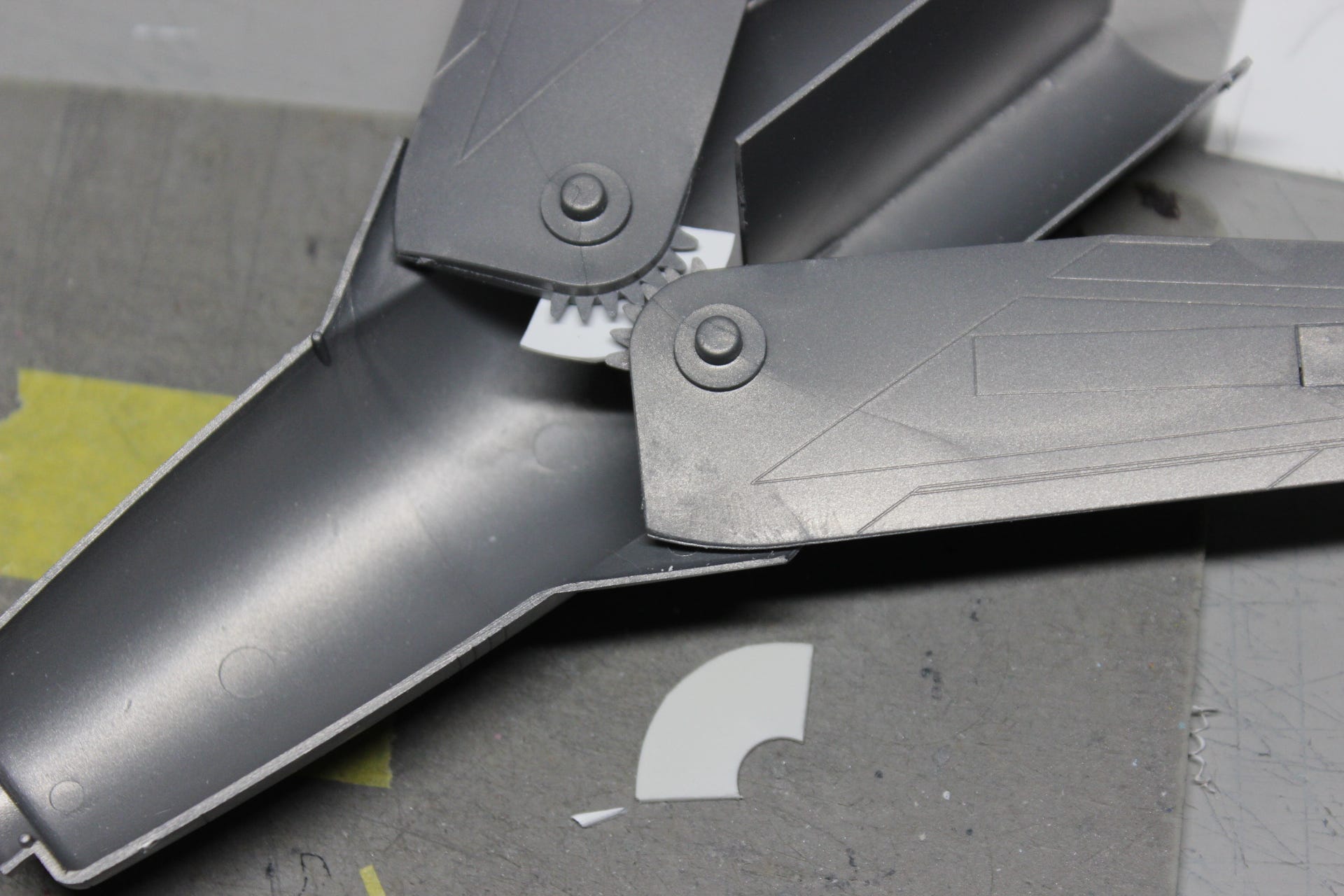
Something else had to be addressed that was a shortcoming of the kit that I discovered while test fitting parts. The gear teeth that insured that both of the variable geometry wings would fold simultaneously were so thin that they could jump over each other when operating and make them go out of sync. Too bad they just didn’t make the teeth a lot thicker... there is plenty of room… as that would have eliminated that problem. I glued some… I don’t know what to call them… tracks? guides?… made from sheet styrene in place to make sure the teeth stayed meshed correctly. They are the little white arc bits you see in the following picture. One is shown installed below the teeth, the other one, not yet glued in place would be glued in above the first one. The idea is that these guides would contact the opposite wing insuring that there could not be flex between the two that would allow the gear teeth to skip.
Next, the main fuselage (body) was glued together and all held in place using rubber bands until the cement cured.
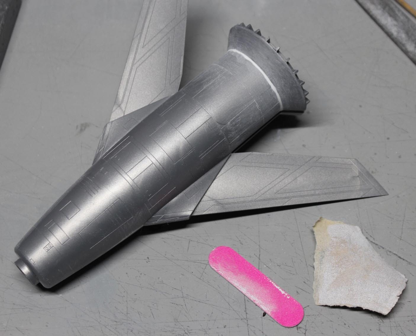
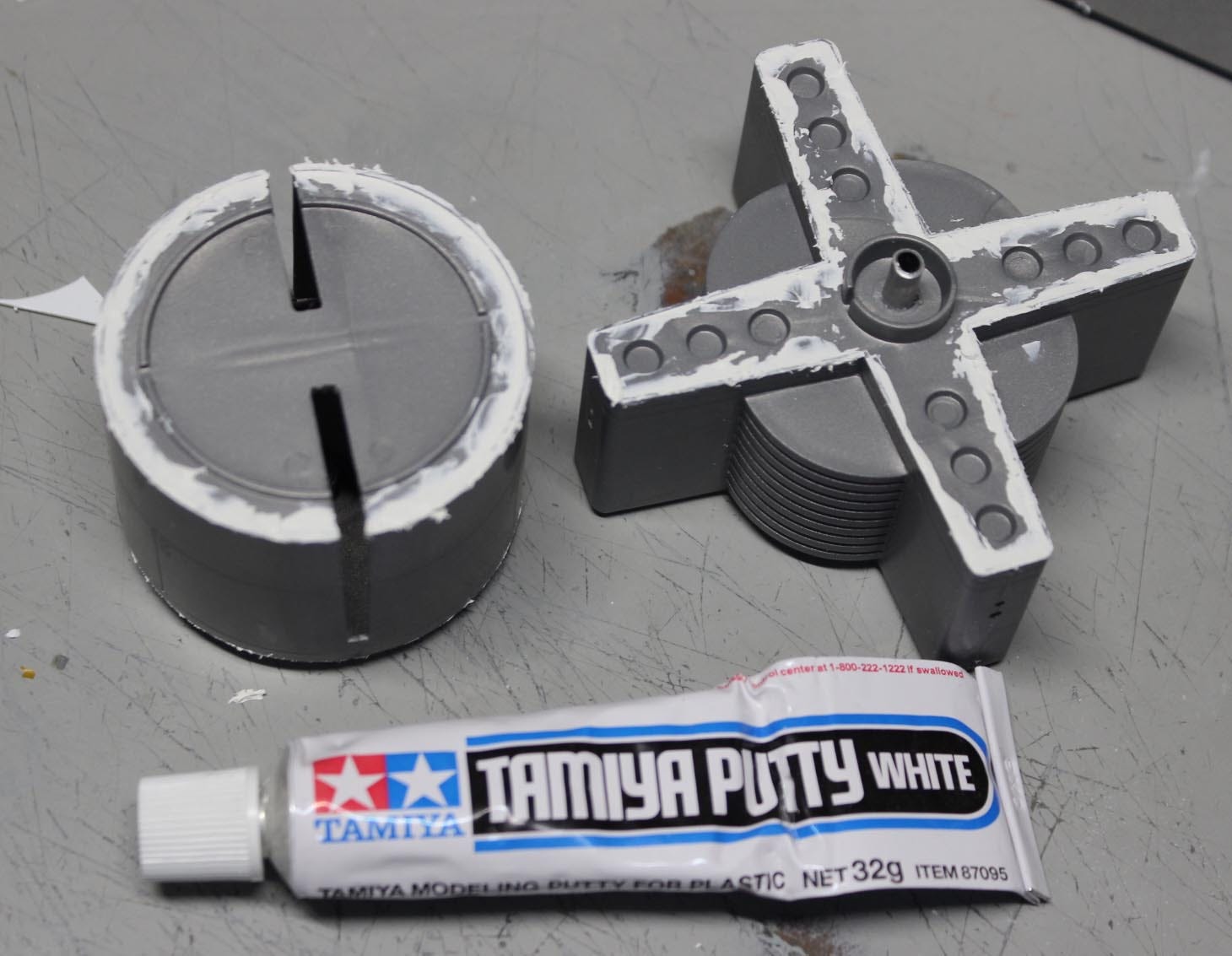
The cone at the bottom of the fuselage had a bit of a gap there which actually should have a blending fillet, so it was puttied and sanded down to look the part.
It was decided there should be a stand made for the model. No stand was included with the kit so the display method was up to me with the following design idea which I suggested to Dan. Because Dan is a reasonably intelligent man, he agreed with me.
;-)
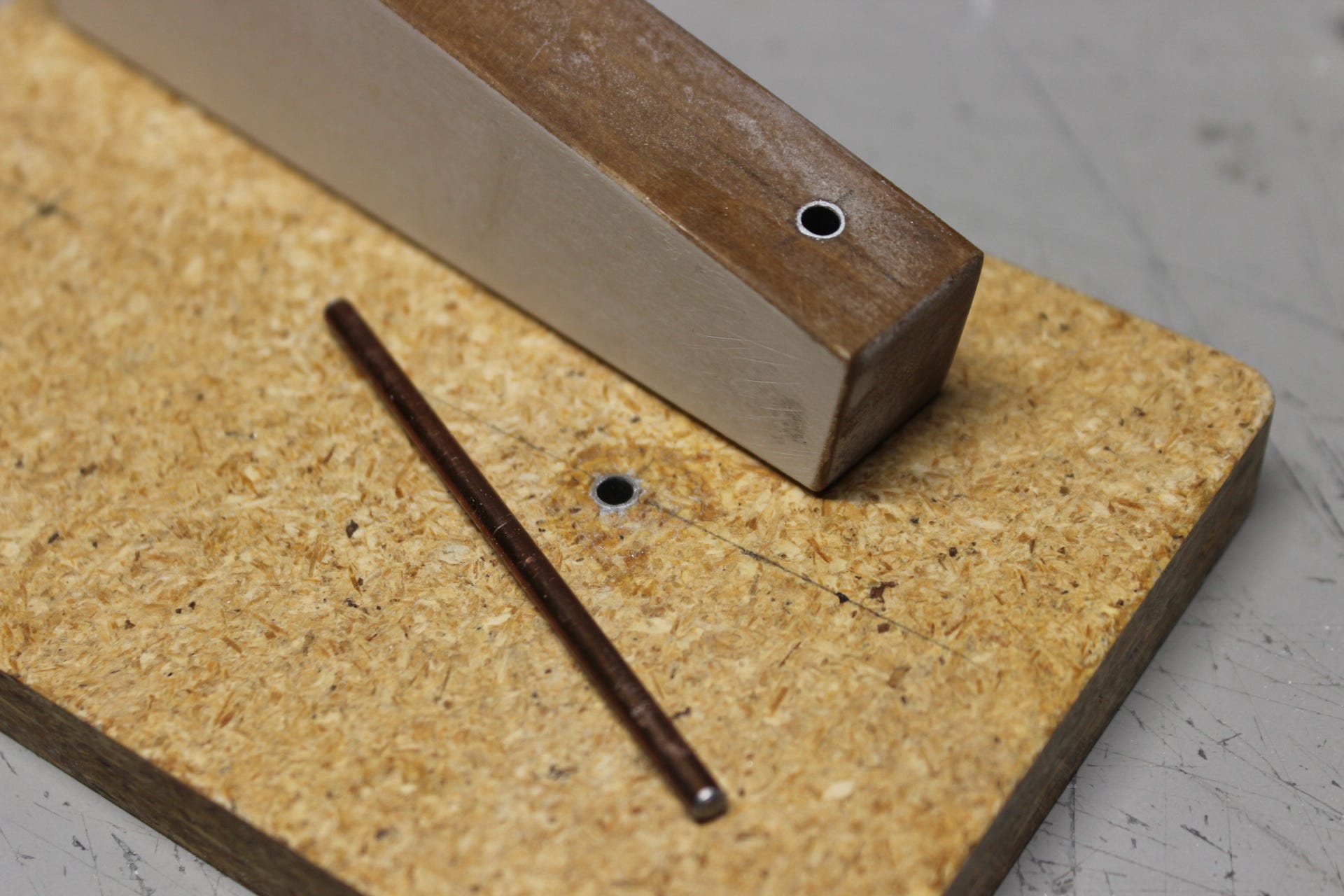
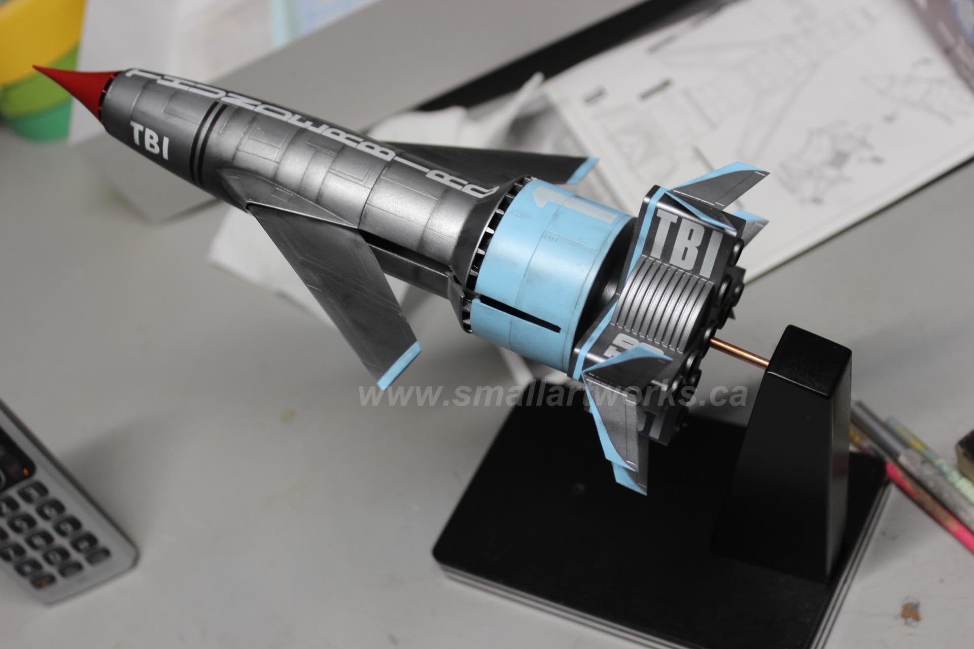
I always like to display a model “in flight” (Well, unless it’s a military tank or some such thing of course! Duh!) and since the TB1 was kind of a “rocket meets aircraft” configuration, I figured a stand that can accommodate both versions would be best. I built a stand so it could be displayed in both launch and flight modes. I grabbed some scrap MDF and particle board, cut them out and installed some aluminum tube into the model’s tail section and the stand that could use a simple piece of rod to mount it.
First, I glued some tube into the tail section like this:
And built a stand to accommodate, like this:
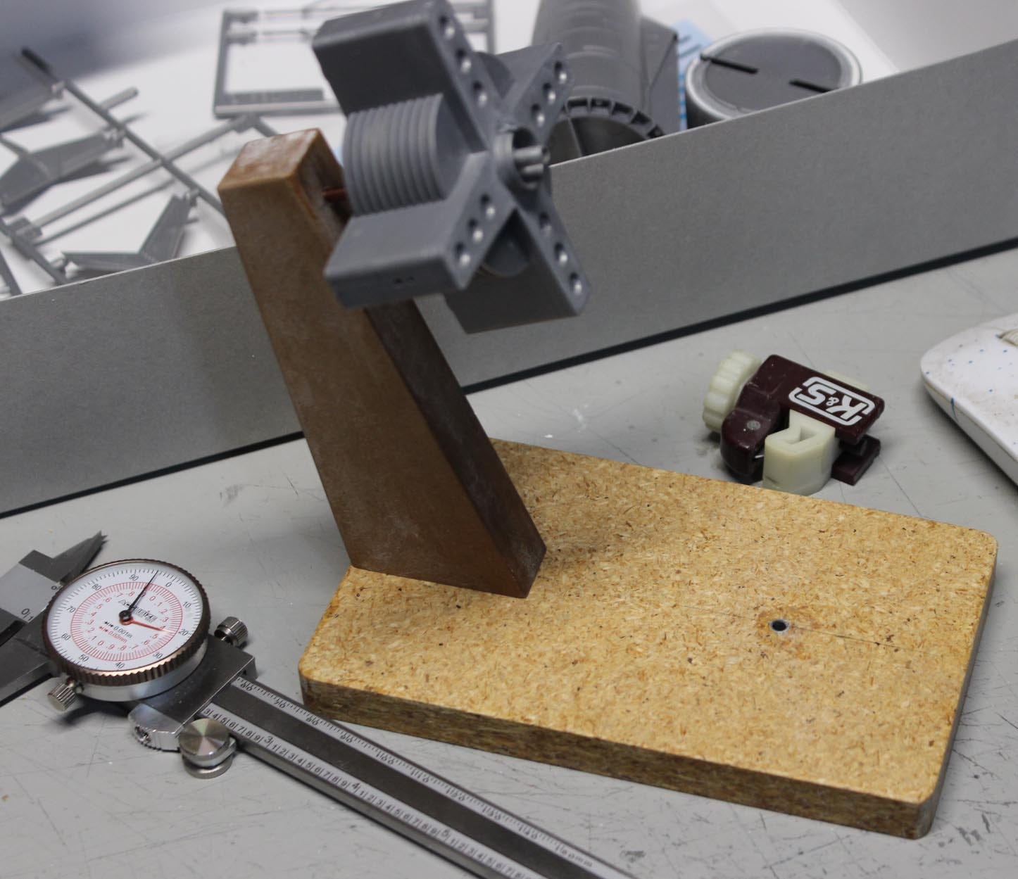
The vertical supporting arm is screwed in place from underneath. Here’s a closeup of the tubes and rod used for support:
Pretty simple, eh?
The model parts were puttied as needed to fill seams and then sanded down.
Then the subassemblies were primed to get ready for finish painting. Masking of some sections were needed where they were to be later glued together which is why some of these parts look kinda buggered:
Now the main painting had to be done. “Dupli-Color” brand automotive lacquer (My favourite but insanely expensive brand of paint, especially here in Taxada… Canatax... whatever) was decanted into an airbrush and sprayed over all parts that had the “gun metal” look. There are three main colours. Gun metal, blue and red (for the nosecone)
But how to go about that in sequence to make it easiest?
Well, the nosecone is a no brainer. Just spray it crimson red on its own and that’s done.
Actually, not all parts were done at the same time. The blue sections had to be dealt with. So do I spray on the gun metal first and then the blue or vice versa? In reality, both sequences were used. For the main fuselage and wings section that was first sprayed in the gun metal. Same for the small winglets you see still attached to the sprue.
For the cylindrical wide section of the body (the part with the big “1” on it), I sprayed that with the blue first. Only the outer cylindrical surface of that is to be blue. So when the blue dried, it was super easy to mask that wall off and then spray the top and bottom of that section with the gun metal. Similar with the main engine section.
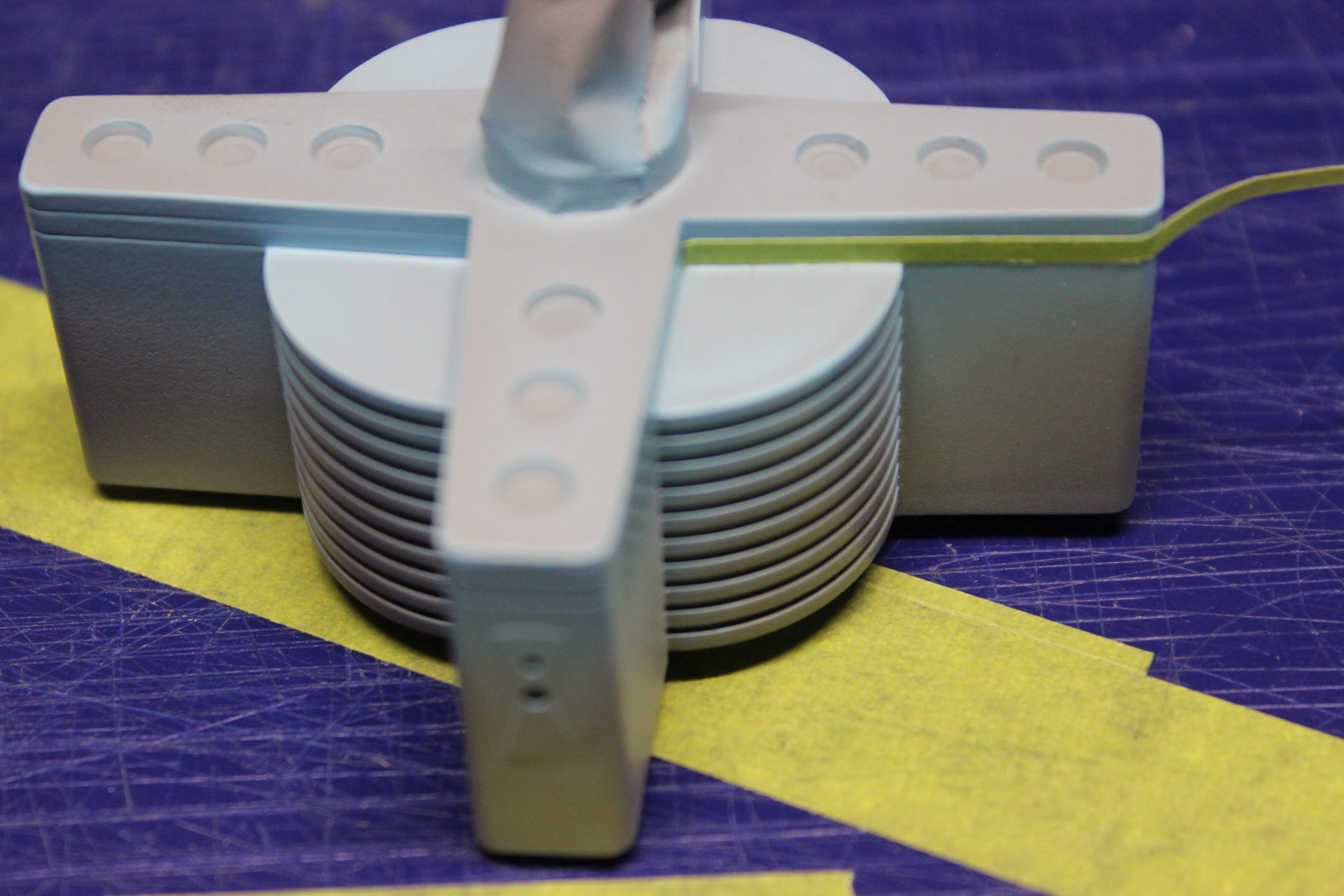
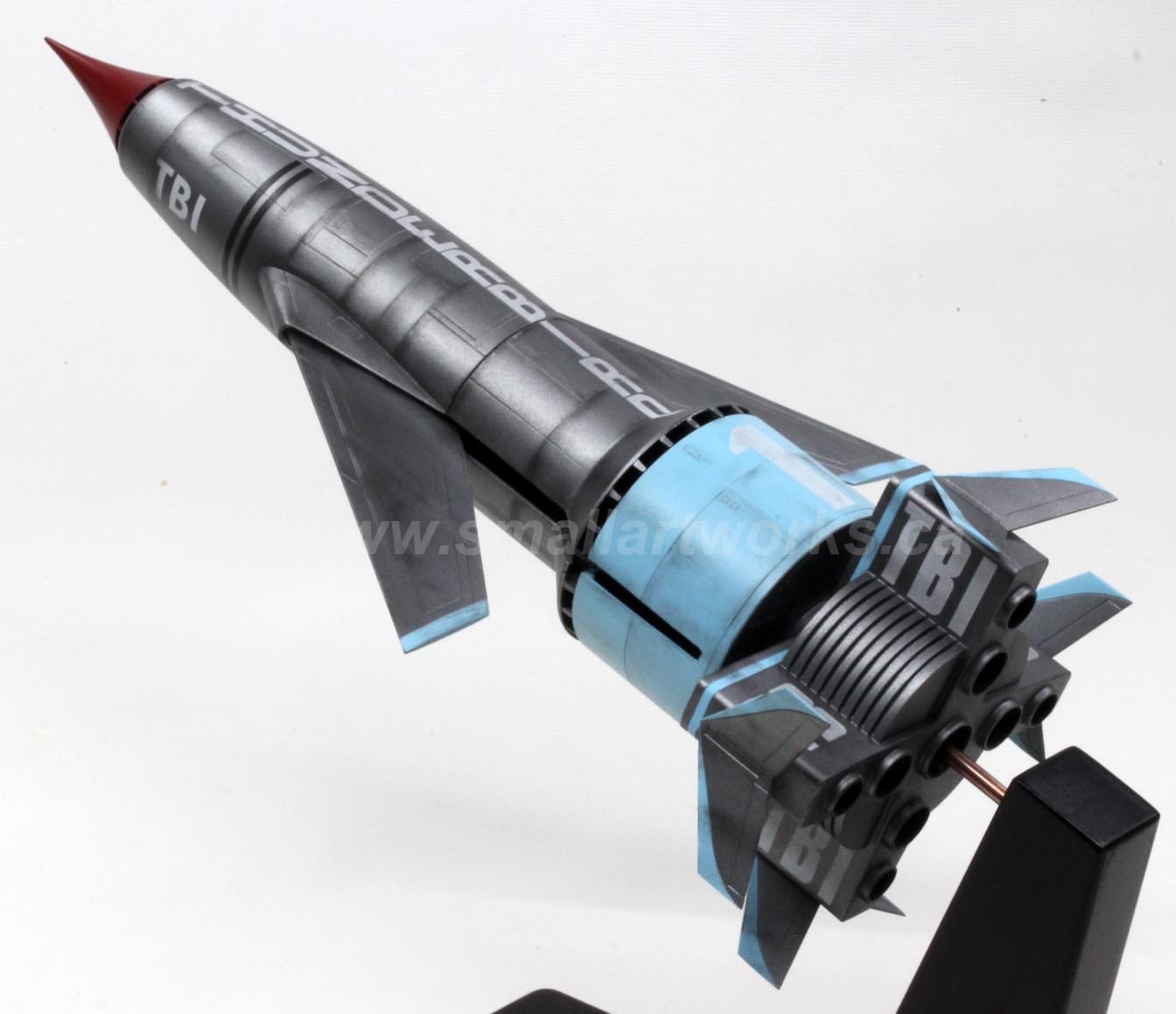
You see, that rear cruciform engine section has that nasty little blue stripe running right around the circumference of it. If I painted the whole thing gun metal, then masking off all that gun metal to spray that blue stripe would be a major pain in the arse. It was MUCH easier to simply spray the blue over the area of the stripe and not care where the overspray went. All I had to do then was slice off some strips of masking tape the width of the blue stripe (which in this case was made easier because the kit had that stripe’s edges scribed in) and protect THAT. Then the entire engine section could be sprayed with the gun metal in one shot. See? Gotta think ahead. We model builders are always looking for the easy way out.
Some people call it efficiency. I, more accurately, call it laziness. ;-)
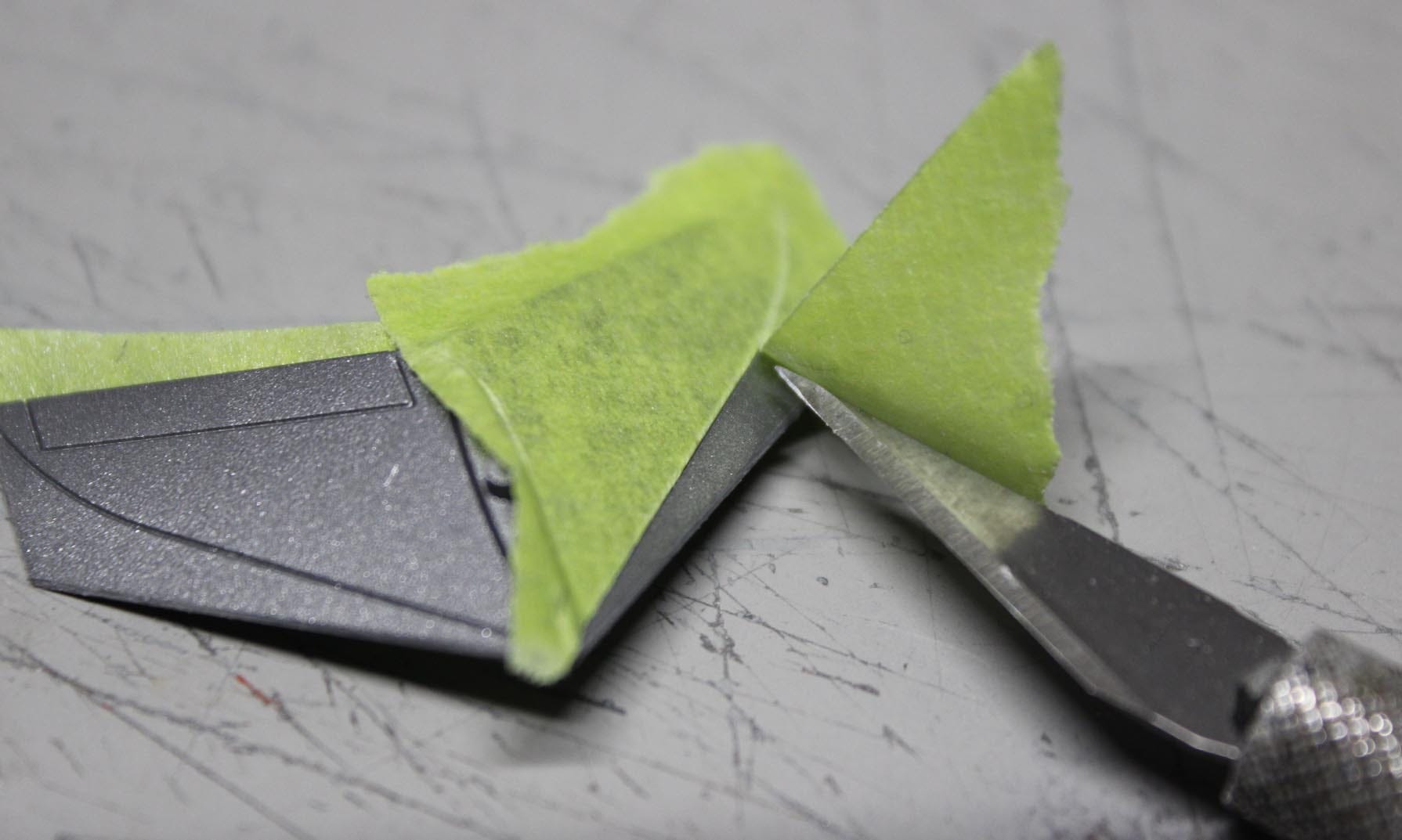
The little winglets that are attached to that engine section were exactly the opposite. Since they could remain attached to the runner, they were all sprayed in one shot together with the gun metal colour. Then, after removing them from the runner, the edges could be cleaned up, then masking tape could be applied and the blue painted sections carefully cut away and removed ready to be sprayed as you see here:
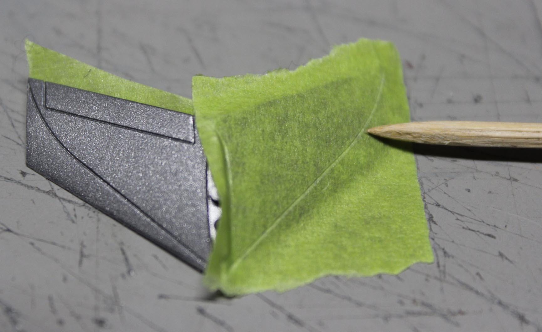
Because the blue sections of the winglets are delineated by a scribed panel line, a toothpick or similar can be used to press the tape into the creases delineating the colour differences and then cut away with an Xacto knife.
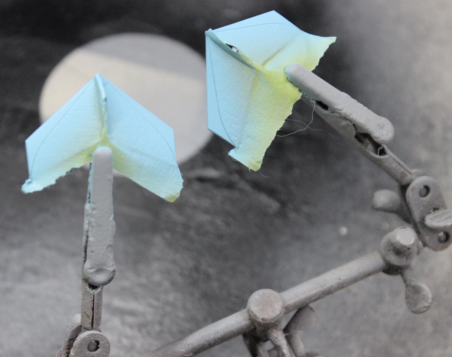
Now the leading edges can be sprayed blue.
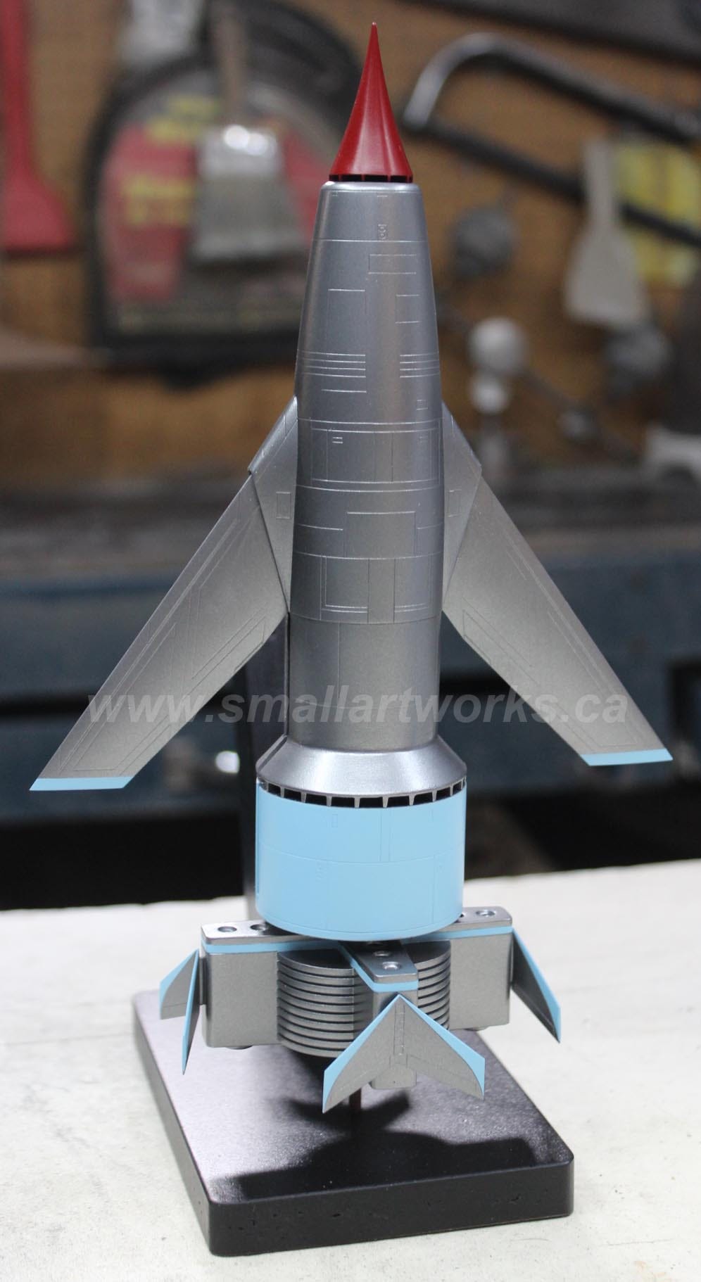
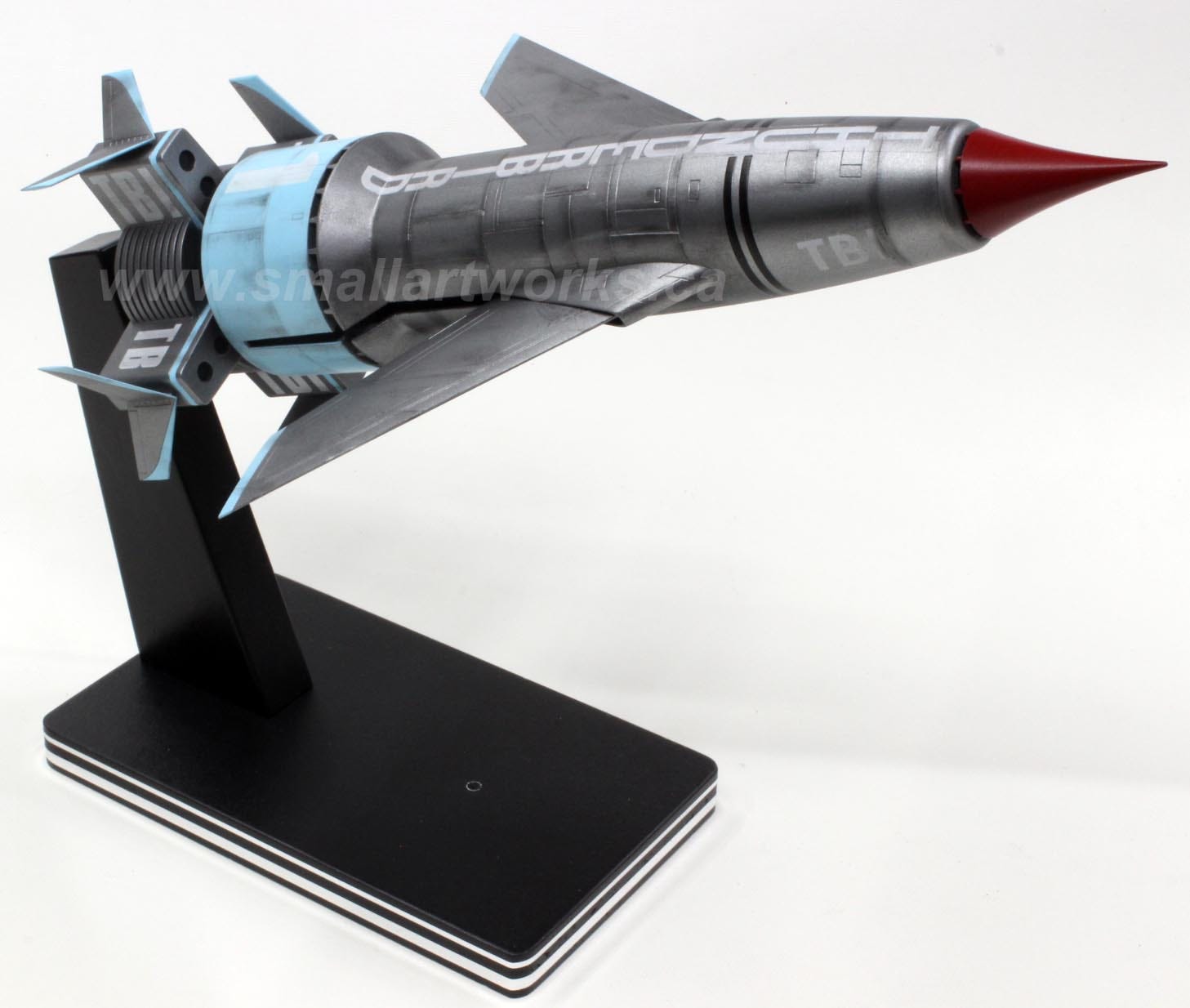
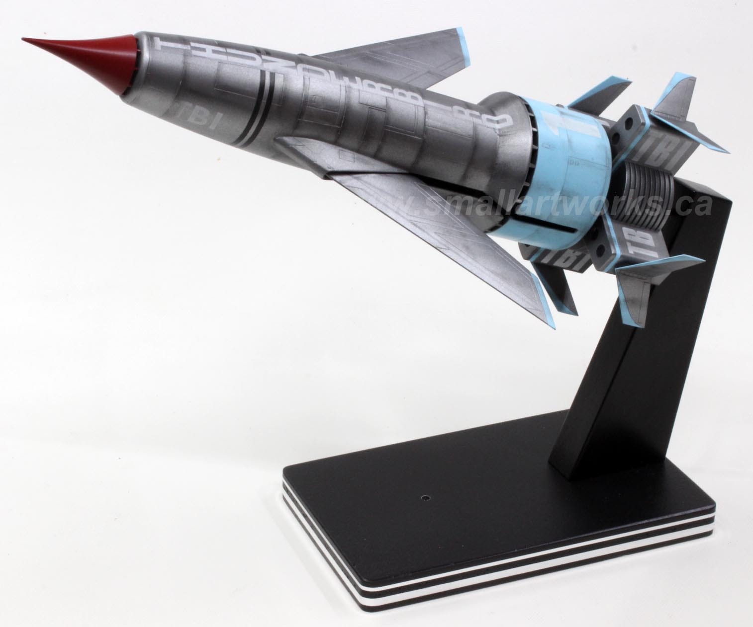
With all painting done, the model is test assembled (without glue!) for the first time, mounted in launch position with the now-painted stand:
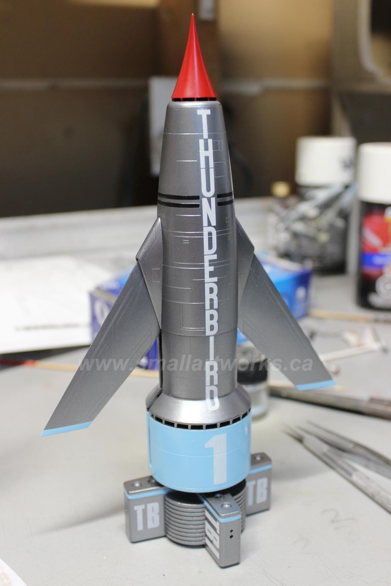
After a while, the decals arrived so it was time to apply those. As expected, V1’s decals went on flawlessly:
Now it’s time to weather the model. I used Conte chalks rubbed on sandpaper to create chalk dust. This dust is then carefully applied using a small paint brush. When satisfied with the weathering, a semigloss clear coat was applied with an airbrush to lock in the chalk weathering and keep it from smearing with handling.

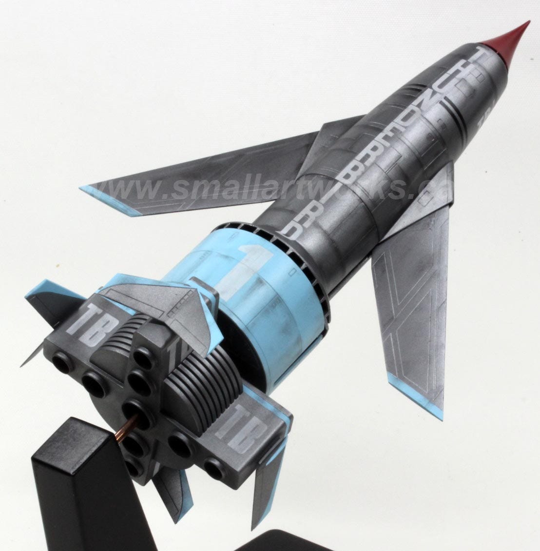
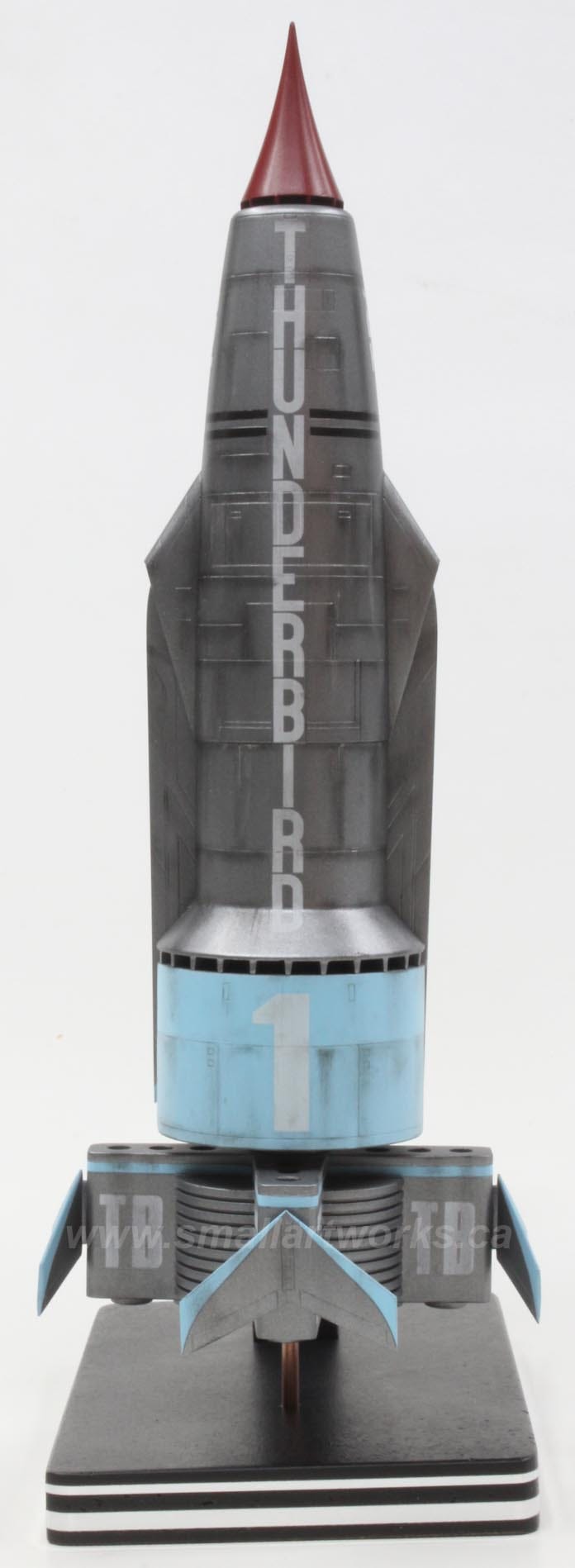
Once the weathering and clearcoat was done, the model was finally fully glued together into its final form and plopped onto its stand for a final evaluation.
Yeah, looks OK I guess... You tell me! Dan liked it anyway, and the customer is the ultimate judge.

I hope you enjoyed this little dip into how to build a relatively simple model kit and use a little research, creativity and dedication to make it a little more special than just building it from the box.
If you like this content, please subscribe and comment.
And remember… if I can do it, you can do it. Take that model kit off the shelf and start BUILDING!
Awesome! I think by now most model makers, and or scifi fans know the changes with FX studio prop models, and how they differ from scene to scene. Fantastic job of compositing the scenes to create a great model.
(looking at my tower of kits) Of couse I can !!
But then again ;-) time.
As always. A fine job. Having seen them i TV - loong time ago - I still have a soft spot for those fellows :-)